2021-22 Sem 2 Project 1: RC circuit step response and frequency response

Expected project duration: 1 week (i.e. 2 lab sessions)

Project type: individual

In today’s labs, we investigate the RC circuit, which is a capacitor in series with a resistor. We will use the signal generator to apply different voltage signals to the RC circuit and the oscilloscope to see how it responds.

A detailed report is not required for this short project, but you will submit a Word document containing five items of evidence to Brightspace. State the following at the beginning of the Word document:

  • Your name
  • The date
  • Module code (ELEC 1011)
  • Project title (“RC circuit step response and frequency response”)

The five items of evidence to include in the Word document are:

  1. Breadboard photograph,
  2. Photo of step response displayed on oscilloscope,
  3. Photo of time constant calculation on paper,
  4. Photo of sinusoidal AC waveforms on oscilloscope,
  5. Excel plot of magnitude response of the RC circuit.

More details about each item of evidence are provided below. No additional text or other content is required in the Word document.

Background theory

You’re already familiar with resistance and with Ohm’s law, which describes the relationship between the voltage across a resistor and the current flowing through it.

v = iR

where v is the instantaneous voltage (in volts) between the terminals of the resistor, i is the instantaneous current (in amperes) flowing through it, and R is the resistance (in ohms). This means that at every moment in time, the current flowing through a resistor is proportional to the voltage across it at that instant. This remains true even when the voltage applied to the resistor is varying over time, as is the case with an AC voltage. When you apply a sinusoidal voltage to a resistor, you get a sinusoidal current with a magnitude that depends on the resistance. The voltage and current waveforms are exactly in phase, which means that they’re perfectly aligned in time – the peak current occurs at the same time as the peak voltage.

The relationship between voltage and current in a capacitor is more complicated.

i=C\frac{dv}{dt}

where v is the instantaneous voltage (in volts) between the terminals of the capacitor, i is the instantaneous current (in amperes) flowing through it, and C is the capacitance (in farads). What this means is that the current is proportional to the rate of change of voltage. So when an AC voltage is applied to a capacitor, the magnitude of the current depends on how fast the voltage is changing.

  • If the frequency of the AC voltage is high (meaning that the voltage is constantly changing very rapidly), then the current will be large because the capacitor doesn’t impede it very much.
  • Conversely, if the frequency of the AC voltage is low (meaning that the voltage is only changing relatively slowly), then the capacitor impedes the current a lot.

This leads us to the concept of impedance which tells us how much an element (resistor, inductor or capacitor) impedes the flow of electric current. We can also calculate the impedance of a circuit made up of any combination of resistors, inductors and capacitors.

Conventionally, impedance values are represented using an upper case letter Z. In general, impedance is a complex number. However, the impedance of a resistor is purely real (i.e. it has zero imaginary part). The impedance of a resistor is simply equal to its resistance:

Z_R = R

where R is the resistance (in ohms) and Z_R is the impedance of the resistor (in ohms).

The impedance of a capacitor is purely imaginary (i.e. its real part is zero). It depends on two things: the capacitance and the frequency of the current.

Z_C =  \frac{1}{j\omega C} = \frac{-1}{\omega C}j

where Z_C is the imedance of the capacitor (in ohms), C is the capacitance (in farads), j is the imaginary unit (i.e. j=\sqrt{1}), and \omega is the angular frequency (in rad/s).

Angular frequency represents the same property of a signal as frequency, but in different units. Whereas frequency is measured in hertz (cycles per second), angular frequency is measured in rad/s (radians per second). When working with impedances, using angular frequencies greatly simplifies the arithmetic.

Frequency, f, in hertz and angular frequency, \omega, in rad/s are related as follows.

w=2\pi f

Last semester, we learned various approaches for analyzing circuits made up of resistors and DC voltage and current sources. In the coming weeks, we will learn how to apply the same techniques to circuits made up of resistors, inductors, capacitors, and sinusoidal voltage and current sources. The key to doing this will be representing the sinusoidal voltages and currents using complex values known as phasors, and by converting all of the resistors, capacitors and inductors into impedances.

If you think of impedance as an extension of the concept of resistance, then a capacitor is “like a resistor” that changes its resistance depending on the frequency of the current flowing through it. High frequencies pass through easily. Low frequencies find it much harder to pass through.

Because impedance is a complex number (having a magnitude and an angle) it also introduces a phase shift between voltage and current waveforms. In a capacitor, the current waveform leads the voltage waveform by exactly 90^{\circ} (equivalent to \frac{\pi}{2} radians) – i.e. one quarter cycle.

Part 1: Construct the RC circuit on the breadboard

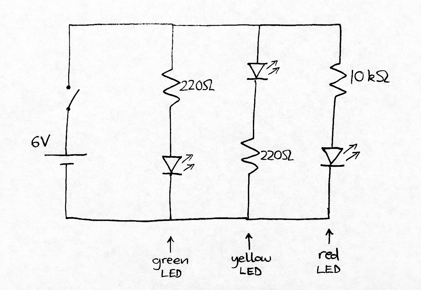
The circuit shown below is the basis for today’s experiment.

  • Your instructor will provide you with the 1 kΩ resistor and 220 nF capacitor.
  • For the voltage source on the left, use the signal generator available in the laboratory.
  • The volt meter symbols on the right represent the two channels of the oscilloscope. Channel 1 is used to measure the input voltage signal applied to the complete RC circuit. Channel 2 is used to measure the voltage across the capacitor on its own.

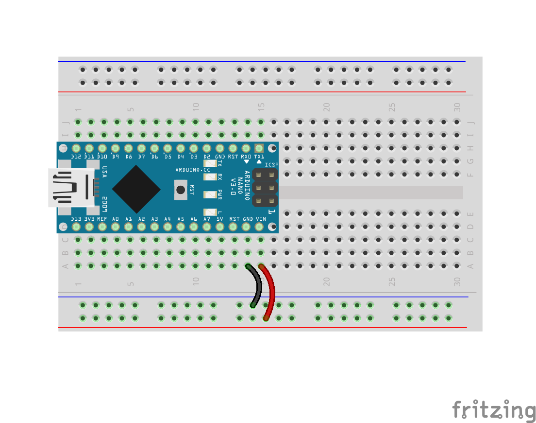
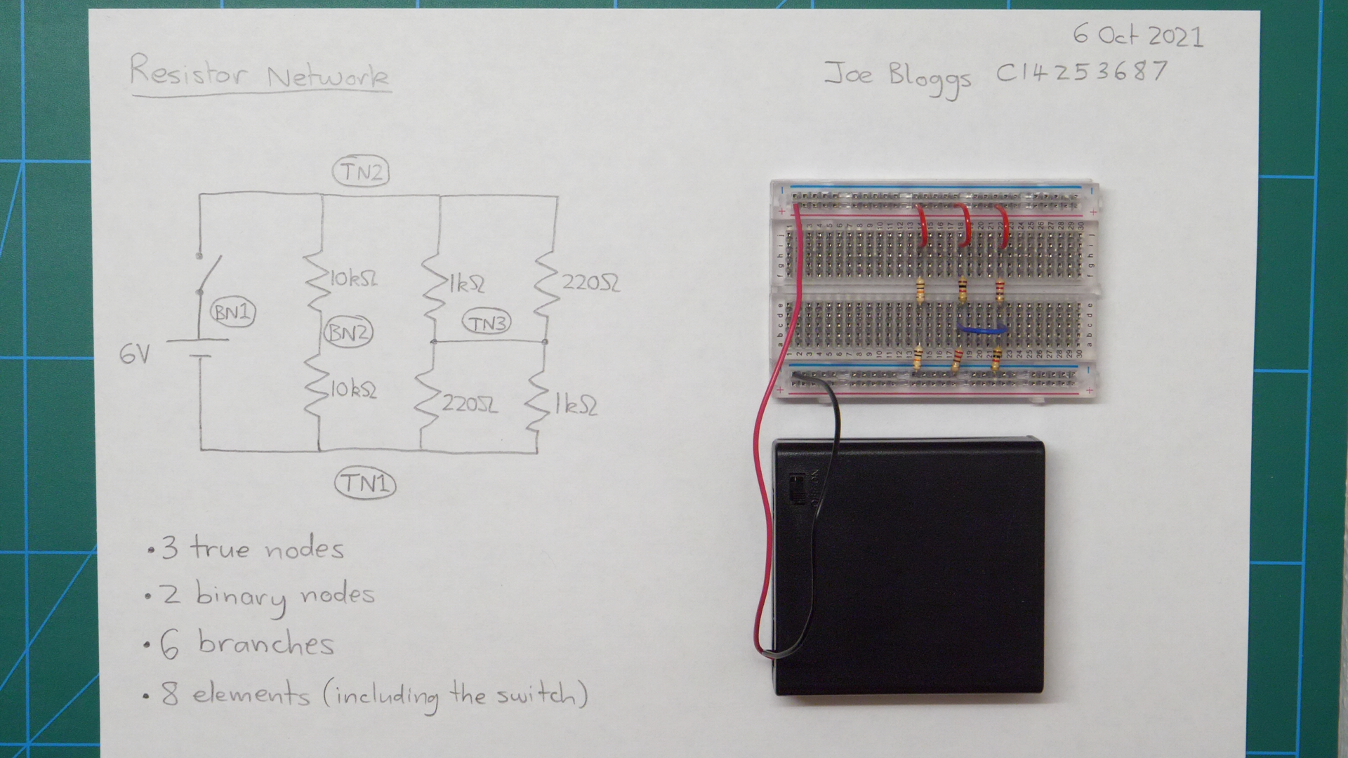
The photo below shows the RC circuit built on a breadboard, with the resistor and capacitor placed in series. The red and black wires at the left side of the photo are supplying the input voltage signal from the signal generator. During this experiment, you will apply several different input voltage signals to see how the circuit responds.

The oscilloscope connections are not shown above, but the two probes should be connected as follows:

  • Connect the ground connection of each oscilloscope probe to the negative rail at the lower side of breadboard.
  • The signal connection for scope channel 1 can be connected to the red rail at the upper side of the breadboard to measure the input voltage coming straight from the signal generator.
  • The signal connection for scope channel 2 can be connected to the circuit node between the capacitor and the resistor (e.g. point h15 on the breadboard in the above photo).

EVIDENCE ITEM 1: Take a clear photograph of your complete breadboard circuit, including the connections to the signal generator and oscilloscope.

Part 2: Step response of the RC circuit

In this part of the experiment, you will apply an input voltage signal to the RC circuit that goes through a step change (increasing abruptly from 0 V to 5 V) and observe how the capacitor voltage changes in response.

The expected step response of the RC circuit is shown above. The black waveform, v(t), is the input voltage signal. The red waveform, v_c(t), is the capacitor voltage, which exhibits the exponential step response.

The input voltage v(t) (black line) increase abruptly, but the capacitor voltage v_c(t) (red line) rises more slowly and approaches the input voltage asymptotically. This red curve is the step response of the RC circuit.

Useful information about a system can be gleaned from its step response. For example, we can measure the time constant of this system from the step response.

To measure the step response of your RC circuit:

  1. Set the signal generator to output a square wave with 5 V amplitude and very low frequency (e.g. 10 Hz).
  2. Display both traces (channels 1 and 2) on the screen of the oscilloscope.
  3. Set the oscilloscope trigger source as channel 1 (the step input).
  4. Set the trigger level to a value in between 0 V and 5 V.
  5. Adjust the time and voltage scaling to display a clear view of the step response.
  6. Estimate the time constant (in seconds) by measuring it from the oscilloscope screen. Refer to the diagram above to see what you need to measure.
  7. On a piece of paper, calculate the expected time constant of the RC circuit, using the formula provided in the diagram above. Write down the time constant measured from the oscilloscope. Do the measured and expected values agree?

Ask your lab instructor if you need help with the controls on the signal generator or oscilloscope.

EVIDENCE ITEM 2: Take a clear photograph of the step response of the RC circuit displayed on the oscilloscope screen.

EVIDENCE ITEM 3: Take a clear photograph of the page showing your time constant calculation.

Part 3: Frequency response of the RC circuit

In this part of the experiment, you will apply voltage signals of different frequencies to the RC circuit and observe how the magnitude and phase of the capacitor voltage vary (relative to the input voltage). You will plot a graph of the magnitude response of the RC circuit.

To begin,

  1. Configure the signal generator to output a sinusoidal waveform with an amplitude of 1 V and a frequency of 1 kHz. Verify that the signal appears correctly on the oscilloscope.
  2. Select the same time and voltage scaling on both channels of the oscilloscope so that you can compare the waveforms directly.
  3. Verify that the capacitor voltage is also sinusoidal. You should see that it has smaller amplitude than the input signal and that there is a phase shift between the two signals.

EVIDENCE ITEM 4: Take a clear photograph of the input voltage (1 V amplitude and 1 kHz frequency) and capacitor voltage waveforms displayed on the oscilloscope.

To plot the magnitude response of the RC circuit, use the oscilloscope to measure the amplitude of the capacitor voltage waveform over a range of frequencies. You may need to adjust the signal generator controls to ensure that the input voltage amplitude remains constant at every frequency. However, the capacitor voltage amplitude is expected to change because the impedance of the capacitor reduces as frequency increases. You will also observe that the phase shift between the voltage waveforms changes with frequency.

Measure the capacitor voltage amplitude at the following frequencies: 10 Hz, 30 Hz, 100 Hz, 300 Hz, 1 kHz, 3 kHz, 10 kHz, 30 kHz, 100 kHz, 300 kHz. Use Excel to tabulate your results and plot a graph of the magnitude response.

  • Label the horizontal axis as “Frequency [Hz]”. You may need to select a log scale on that axis.
  • Label the vertical axis as “Amplitude [V]”.
  • Add a suitable title to the graph (e.g. “Magnitude response of RC circuit”).

EVIDENCE ITEM 5: Copy and paste your Excel graph into your Word Document.

Finally, submit your complete Word document containing the five items of evidence to Brightspace.

2021-22 Sem 1 Project 5: Analog Music Synthesizer

Expected project duration: 3 weeks (6 lab sessions)

At the end of this project you should be able to:

  • Build an voltage oscillator circuit on a breadboard using an opamp.
  • Use an oscilloscope to debug and test your oscillator circuit.
  • Adapt the oscillator circuit to produce musical sounds from a loudspeaker.

This project comprises two parts:

  1. Individual element: Initially, you will build and test a relaxation oscillator circuit on your breadboard (circuit diagram provided below). You will submit evidence of your working circuit in Brightspace (provisional deadline Wed 1 Dec 2021).
  2. Team element: You will work with your teammates to develop an analog music synthesizer that you will use to perform a piece of music for a competition in the final week of the semester (week beginning Mon 13th Dec).

Further details about both elements of the project will be provided in class and this post will be updated in the coming days with details about what evidence you will need to submit.

Code examples from today’s class

This is the example circuit we looked at in class. An Arduino Nano reads signals from two TCRT5000 infrared reflective sensors and then control two DC motors via an SN754410NW quad half H-bridge integrated circuit (IC).

We also looked at the physical layout of the pins on the SN754410NE:

  • The two centre pins on each side of the chip are ground connections.
  • The pins either side of the ground pins are outputs.
  • Each output pin is controlled by the input pin right next to it (on the other side to the ground pin).
  • Corner pins 8 and 16 are connected to the positive voltage supply. Different voltages can be connected to these two pins where the motors require a higher voltage than the control circuit, but that is not the case here.

This code example illustrates the use of a new function to control the direction of both motors (forward, reverse or stop) with a single function call. The benefit of doing this is that the low-level details about which pins need to be set high and low are encapsulated in the motors function, which makes the loop function much more readable.

//
// 2-sensor control of Arduino robot
// Written by Ted Burke - last updated 17-Nov-2021
//

void setup()
{
  // motor control pins
  pinMode(2, OUTPUT); // left motor forward
  pinMode(3, OUTPUT); // left motor reverse
  pinMode(4, OUTPUT); // right motor forward
  pinMode(5, OUTPUT); // right motor reverse

  // Open serial connection to PC
  Serial.begin(9600);
}

void loop()
{
  motors(1,1); // left motor forward, right motor forward
  delay(2000);

  motors(-1,-1); // left motor reverse, right motor reverse
  delay(2000);

  motors(1,0); // left motor forward, right motor stop
  delay(2000);
}

// This function sets the direction of both motors
void motors(int left, int right)
{
  // Control left motor
  if (left > 0)
  {
    digitalWrite(2, HIGH); // left motor forward
    digitalWrite(3, LOW);    
  }
  else if (left < 0)
  {
    digitalWrite(2, LOW);  // left motor reverse
    digitalWrite(3, HIGH);
  }
  else
  {
    digitalWrite(2, LOW);  // left motor stop
    digitalWrite(3, LOW);
  }

  // Control right motor
  if (right > 0)
  {
    digitalWrite(4, HIGH); // right forward
    digitalWrite(5, LOW);    
  }
  else if (right < 0)
  {
    digitalWrite(4, LOW);  // right motor reverse
    digitalWrite(5, HIGH);
  }
  else
  {
    digitalWrite(4, LOW);  // right motor stop
    digitalWrite(5, LOW);
  }
}


Building a colour sensor module using the TCRT5000 infrared reflective sensor and terminal block

The TCRT5000 is an infrared reflective sensor in a small black plastic casing with four legs, with one “blue eye” and one “black eye”. The blue eye is an infrared LED which emits a beam of infrared light when electric current flows through it. The black eye is a phototransistor which detects infrared light. When the sensor is close to a surface, some of the emitted light is reflected back and detected by the phototransistor, but the amount of light reflected back depends on the colour of the surface. This can be used to sense the colour of a surface. This article explains how to use the TCRT5000 (with resistors, wires and terminal block) to build a 3-wire colour sensing module.

  • Lay out the parts shown in the image below. The three wires visible at the bottom of the image are the long red, blue and black wires.
  • “TCRT5000” is written in tiny letters on one side of the colour sensor – make sure that side is facing downwards (towards the table).
  • The two legs of the TCRT5000 that are now higher off the table (i.e. closer to the camera in the image below) should be carefully bent towards each other until they meet.
20151028_023213

Insert the components and wires into the terminal block as shown in the images below and tighten each terminal with a screwdriver to hold them all in place.

20151028_022117
20151028_022211
20151028_022311

To connect the sensor module to an Arduino breadboard circuit, connect the three wires as follows:

  • Connect the red wire to the positive (red) rail.
  • Connect the black wire to the negative (blue) rail.
  • Connect the blue wire to an analog input pin on the Arduino, e.g. pin A0.

2021-22 Sem 1 Project 4: Track TT

Expected project duration: 3 weeks (i.e. 5-6 lab sessions)

In this team project, you will work in a team of three to design and build a small autonomous robot vehicle to compete in a time trial (TT) competition. The robot will have to navigate autonomously along a clearly marked winding track from one end to the other. The project will conclude with a competition in which we measure how long it takes each team’s robot to complete the task. Your team will record a 3-minute video presentation describing the design of your robot.

The project will include the following elements (among others):

  • Arduino programming
  • Motor control
  • Mechanical design
  • Use of one or more TCRT5000 infrared sensors to detect the track

The project grade will be based on three factors:

  1. Performance of your team’s robot in the competition
  2. Quality of your presentation
  3. Tutor observation of your individual contribution to the group work process

Video presentation guidelines:

  • Each team member must present one minute (60 seconds) of the team video.
  • Most teams will have three members, but teams with two or four members can adjust the overall video duration so that each team member presents for 60 seconds. Teams with two members may, if they wish, extend each student’s presentation time to 90 seconds.
  • The team should agree in advance what topics each team member will cover.
  • It’s up to each team member whether they are visible in the video, but every team member must speak in their section of the video. Quality of spoken presentation will be an element in the formal grade.
  • Quality of visual presentation will be an element in the formal grade.
  • Your team video must be uploaded to YouTube and set as publicly visible. It can be unlisted. Each team member will confirm that they contributed to the team video by submitting the YouTube link to Brightspace (same link for all team members).

Results will be ranked based on the time taken by each robot to complete the task (as measured by the referee), as well as compliance with the rules set out below.

Useful reading:

Competition Rules

Competitors are permitted (at the discretion of the referee) to attempt the task multiple times, whether to complete the task for the first time, or to improve upon a previously recorded attempt. Priority may be given to competitors who have not yet recorded a successful attempt.

The track will be a dark stripe on a light-coloured background.

At the beginning of a time trial attempt, the team places their robot over the start end of the stripe. Some part of the robot must be directly above the end of the track when the referee starts the clock.

The robot follows the track from the start to the finish end of the stripe, keeping some part of itself directly above the stripe at all times. Competitors are forbidden from touching or otherwise influencing the robot during the time trial – the robot must be complete the task autonomously.

The clock stops as soon as any part of the robot is directly above the finish end of the stripe. The robot does not need to come to a halt.

If the robot leaves the track at any point (i.e. no part of the robot is directly above the track), that attempt at the time trial is null and void.

The Track

  • The track will be marked with a clearly visible stripe on a horizontal surface.
  • The track will be a dark stripe on a light background.
  • The width of the stripe will be no less than 4cm and no greater than 6cm.
  • The track consists of five straight sections, each at least 50cm in length.
  • At every meeting point between two straight sections, the track turns a right-angled corner (i.e. 90 degrees). At each corner, the inner and outer edges of the track will each form a 90 degree angle (i.e. neither edge of the track is rounded at the corner).
  • As the robot travels along the track from beginning to end, the corners are as follows: left turn, left turn, right turn, right turn.
  • The recorded result for the time trial will be the time elapsed between the last moment when the robot was above the start end of the stripe and the first moment when the robot is above the finishing end of the stripe.
  • The robot must remain in contact with the horizontal surface throughout the time trial.
  • It is not permitted to touch, influence or otherwise interfere with the robot during the time trial – it must operate completely autonomously.
  • If the robot leaves the track at any point during the time trial, that attempt is null and void. The robot does not need to be in physical contact with the track throughout the attempt, but some part of the robot must always be directly above some part of the track.

Robot specification

  • The maximum permitted size of the robot is a cube 150 mm on all sides (i.e. 150 mm × 150 mm × 150 mm). At every moment during an attempt, every single part of the robot (including loose wires, etc.) must fit within an upright 150 x 150 x 150 mm cube. Upright means that two sides of the cube are horizontal and four sides are vertical. Note that this size limit is very strictly enforced.
  • The maximum permitted mass of the robot is 500 g. This weight limit is strictly enforced.
  • The only permitted power source for the robot is 4 × AA batteries (e.g. the battery pack provided in the RoboSumo kit).
  • Competitors are permitted to source additional components and materials for use in their robot, at their own expense. However, the maximum permitted budget for parts used in a robot during the time trial is €20 (of the competitors’ own money). This excludes the cost of parts supplied by the college and materials that were obtained for free (provided that similar materials could easily be obtained for free by other competitors). Note that you do not need to spend any money to complete this challenge. Also, please note that any money you choose to spend will not be reimbursed by the college.

Non-compliant robots and late entries

  • Robots that fail to comply with the above specifications may still be permitted to record a ranked time, at the discretion of the referee. However, their results will be ranked below those of compliant robots that completed the task in the same week, irrespective of the time recorded.
  • Results for teams that complete the task after the end of the formal competition may, at the discretion of the referees, be added to the ranking. However, they will be ranked below teams that completed the challenge during the competition, unless some exceptional circumstances apply (e.g. certified medical absence).

Example TrackTT video

Note that the following video shows a white track on a dark background, but the track used in this project will be a black track on a light-coloured background.

Summary of ranking criteria:

Ranking of results will be according to the following criteria, in order of decreasing precedence:

  1. Robots that are fully compliant with the above robot specification during their ranked attempt will rank above robots that are non-compliant during their ranked attempt.
  2. Robots will be ranked according to the time taken to complete the task. Robots that complete it quicker will be ranked higher.

Referees and conduct of competitors

  • Every EEPP module lecturer is a competition referee. The module lecturers may also nominate additional referees.
  • Competitors must follow the referee’s instructions during an attempt.
  • Competitors who repeatedly fail to follow the referee’s instructions, or who engage in rude or offensive behaviour during the competition may be suspended or disqualified at the discretion of the referee(s).
  • The referees will aim to treat all competitors fairly. Where a difference of opinion arises, competitors must always respect the decision of the referee. Once the referee makes a decision, competitors must refrain from further argument on the matter.
  • The referees reserve the right to amend the competition rules or ranking criteria in individual cases, should the need arise (e.g. where a student is absent for medical reasons). Amendments may be applied at the time of the competition or subsequently, which may affect the competition ranking.

2021-22 Sem 1 Project 3: Motor control

Expected project duration: 1 week (i.e. 2 lab sessions)

At the end of this project, you should be able to:

  • Solder wires onto the terminals of a motor.
  • Perform unidirectional speed control of a DC motor using an Arduino and a MOSFET transistor.
  • Perform bi-directional speed control of a DC motor using an Arduino and an SN754410 driver IC.
  • Use an oscilloscope to visualise oscillating electrical voltage signals.

There are three items to be submitted to Brightspace for assessment:

  1. A Word document containing the following evidence (additional details below):
    • Photo of the wires soldered onto your motor.
    • Photo of your breadboard circuit for Task 1.
    • Working code for Task 1.
    • Photo of your breadboard circuit for Task 2.
    • Working code for Task 2.
  2. A link to a YouTube video showing that Task 1 is complete (details below).
  3. A link to a YouTube video showing that Task 2 is complete (details below).

Project Description

In this project, we explore two ways of controlling a motor with a program running on a microcontroller. In the first task, we use a MOSFET transistor to interface the motor to the Arduino Nano in a way that facilitates unidirectional speed control. In the second task, we use a driver IC to perform bi-directional control of the motor. You will also learn to do some simple soldering and to visualise oscillating electrical signals on an oscilloscope.

Task 1: Unidirectional control of a DC motor

The video below provides some background information for this task.

Perform the following steps:

  1. Solder 20 cm long wires onto the terminals of your motor. You can choose whatever wire colour you like, apart from red or black.
  2. Find the datasheet for the IRFZ44N transistor online, so that you can identify which pin is which.
  3. Build the circuit shown in the diagram above on a breadboard. The circuit should be neat and the wires should be appropriately colour-coded. Please pay special attention to correct use of red and black wires.
  4. Program the Arduino to perform the following sequence of LED and motor actions:
    1. LED off and motor driving at 25% duty cycle for 2 seconds.
    2. LED off and motor driving at 50% duty cycle for 2 seconds.
    3. LED off and motor driving at 100% duty cycle for 2 seconds.
    4. LED on and motor stopped for 4 seconds.
  5. Use the oscilloscope to visualise the pulsed signal being emitted from Arduino pin D3. Your lecturer will demonstrate how to do this in the lab.
  6. Record a video showing your circuit performing the above sequence, followed by the oscilloscope displaying the pulsed signal from pin D3 for each state of the system.
  7. Upload the video to YouTube and submit the link to the Brightspace assignment.
  8. Open a new Word document. Insert a heading with your name, student number, the date, the name of this module and the title of this project.
  9. Take a clear photograph of the wires soldered to your motor and add it to the Word document.
  10. Take a clear photograph of your breadboard circuit and add it to your Word document.
  11. Add your working Arduino code for Task 1 to the Word document. Ensure it is neatly formatted and includes clear and accurate comments.

Task 2: Bi-directional control of a DC motor

The videos below provide background information for this task.

Perform the following steps:

  1. Find the datasheet for the SN754410 IC online and use it to identify the correct pin for each connection to the chip. Try googling “SN754410 datasheet” and look for a PDF result.
  2. Build the circuit shown in the diagram above on a breadboard. Note that the final connection between Arduino pin D6 and pin 9 on the SN754410 chip is not shown in the diagram above, but must be included in your circuit to facilitate speed control (as explained in the video). The circuit should be neat and wires should be appropriately colour-coded (please pay special attention to correct use of red and black wires).
  3. Program the Arduino to perform the following sequence of LED and motor actions:
    • LED off and motor driving forward at 50% duty cycle for 3 seconds.
    • LED on and motor driving forward at 100% duty cycle for 2 seconds.
    • LED off and motor stopped for 3 seconds.
    • LED off and motor driving in reverse at 50% duty cycle for 3 seconds.
    • LED on and motor driving in reverse at 100% duty cycle for 2 seconds.
    • LED off and motor stopped for 3 seconds.
  4. Use the oscilloscope to visualise the pulsed signal being emitted from Arduino pin D6.
  5. Record a video showing your circuit performing the above sequence, followed by the oscilloscope displaying the pulsed signal from pin D6 for each state of the system.
  6. Upload the video to YouTube and submit the link to the Brightspace assignment.
  7. Take a clear photograph of your breadboard circuit and add it to your Word document.
  8. Add your working Arduino code for Task 2 to the Word document. Ensure it is neatly formatted and includes clear and accurate comments.
  9. Submit your Word document to the Brightspace assignment.

2021-22 Sem 1 Project 2: LED Flash Challenge

Expected project duration: 1 week (i.e. 2 lab sessions)

At the end of this project, you should be able to:

  • Build a simple breadboard circuit with the Arduino nano microcontroller development board,
  • Write simple programs to run on the Arduino Nano,
  • Configure Arduino pins as digital outputs and set their voltages high and low (e.g. to switch LEDs on and off).
  • Convert between decimal and binary numbers.

There are four items to be submitted to Brightspace for assessment:

  1. Screenshot of the LED Flash Challenge validator web page displaying the congratulations message with your correct team number.
  2. A photo of your breadboard circuit.
  3. The .ino file containing your complete working code. Your code should be neat, correctly indented and clearly commented.
  4. A link to a YouTube video showing your all of your team’s circuits working at the same time. You can use your battery pack to power your circuit when it’s plugged out from the PC. One YouTube video for the whole team is sufficient, but every team member should upload the link to the video.

Project Description

This project is a short competitive puzzle called the LED Flash Challenge. In this challenge, doing well means two things: getting it working quickly and, more importantly, trying to understand what you’re doing.

You’ll work in a team to solve this puzzle and complete the challenge, but each member of your team will build and program his/her own Arduino circuit. The challenge consists of two tasks:

  1. Build a simple breadboard circuit for the Arduino Nano and program it to blink a light-emitting diode (LED) on and off.
  2. Add a second LED to the circuit and reprogram the Arduino to transmit your team number as a binary sequence using a series of LED flashes.

The first task is very prescriptive, which means that we’ll basically tell you exactly what to do, but to complete the second task you’ll need to think for yourselves. To complete the second task, you will require a team number – this will be assigned to you by your lecturer.

Task 1: Blinking LED

This task is relatively straightforward and shouldn’t take you too long to get working. Before beginning, make sure your breadboard is the same way around as the picture below.

The first component in the circuit is the Arduino Nano, which is a simple computer in a tiny package. In the coming weeks, we will program the Arduino to read signals from different sensors and to control motors and electromagnetic coils. In this project, you will use the Arduino to control some flashing LEDs.

Make sure your Arduino is the right way around, with the mini USB socket at the end of the breadboard (row 1). Place the breadboard flat on a hard surface before pushing the Arduino into the board. The pin marked D12 should be in breadboard hole H1. Some Arduinos can be very difficult to insert into the breadboard, so if you’re having problems just ask for help because you might have just received a particularly tricky one.

As we learned previously, on each side of the breadboard there are two long rows of holes which are connected along the full length of the board. These rails are used to distribute the supply voltage to different parts of the circuit. The blue line marks the negative rail (0V); the red line marks the positive rail (5V in this circuit). The Arduino draws its power from these rails.

  • Connect a short black wire between A14 and the negative (blue) rail.
  • Connect a short red wire between A15 and the positive (red) rail.

The first thing we’ll control with the Arduino is a green light-emitting diode (LED). To do this, we’ll turn the Arduino pin marked D2 into a digital output which means that the program running on the Arduino can set it high (5V) or low (0V). When the pin is set high, a small electrical current flows through the green wire, through the green LED, and finally through the resistor to ground (the negative rail).

  • Insert a green wire between I11 and A18.
  • Insert a green LED between E18 and E19. The LED is a one-way valve for electricity, so it must be the right way around. Inside the green plastic bead, if you look carefully you’ll see that each leg is connected to a kind of a flat plate. As shown in the image below, the leg connected to the larger plate should be in E19.
  • Insert a 220 Ω resistor (colour code  REDREDBROWNGOLD ) with short legs between B19 and the negative (blue) rail.

We’re ready to run a program on the Arduino to flash the green LED on and off.

  • Double-click the Arduino icon on the desktop to launch the Arduino IDE (integrated development environment).
  • NOTE: If you’re working on your own laptop, you can download the Arduino IDE from https://www.arduino.cc/en/software (be sure to select the download for “Windows Win 7 and newer“).
  • Delete the example code that appears by default in the editor.
  • Type the following code into the Arduino IDE editor.

Before running the program on the Arduino Nano, you need to select the correct version of Arduino.

  • Under the “Tools” menu, enter the “Board” sub-menu and select “Arduino Nano” or “Arduino Nano w/ ATmega328” as shown in the image below.
  • Under the “Tools” menu, enter the “Processor” sub-menu and select “ATmega328P (Old Bootloader)”.
  • Under the “Tools” menu, enter the “Port” (or “Serial Port”) sub-menu and select whatever COM device is listed there, as shown below. If the “Port”/”Serial Port” sub-menu is not accessible, please ask your lecturer to check your machine because the Arduino drivers may not be correctly installed.

To download and run the program on the Arduino, click the right-facing arrow button on the toolbar of the Arduino IDE:

At this point you should hopefully see the green LED flashing on and off slowly. If it’s not flashing and you can’t figure out why, please ask your lecturer to check what’s wrong.

Once your LED is blinking, there are four things you need to understand in the code before moving on:

  1. How one of the Arduino pins (D2) was turned into a digital output.
  2. How the LED is turned on.
  3. How the LED is turned off.
  4. How to delay the program for a specified number of milliseconds, so that the rate of the LED blinking can be controlled.

Once you understand these four things, you have finished this part of the task (the easy part) and it’s time to move on to the main part of the LED Flash Challenge.

Task 2:

In this part, you’re going to modify your circuit to create a simple optical transmitter, which transmits a digital message (a sequence of 1s and 0s) as a series of LED flashes.

The message that you’ll transmit will be 2 bytes long (a byte is 8 bits, or 8 ones and zeros) and it will contain your team number (byte 1) followed by a second number, which is calculated by subtracting your team number from 255 (byte 2).

For example, if your team number is 79…

  • byte1 = 79
  • byte2 = 255 – 79 = 176
  • byte1 + byte2 = 255

Here, let me explain how binary numbers work…

Try doing some independent research on binary numbers. You’ll find a lot more great stuff on YouTubeWikipedia, etc.

Specifically, you need to do the following:

  1. Modify the code to create a second digital output pin.
  2. Extend the circuit by adding a second LED (with current limiting resistor) to that digital output pin.
  3. Convert your team number into an 8-bit binary number. This is byte 1 of your message.
  4. Calculate the required value of byte 2 (so that byte1+byte2 = 255) and write it as an 8-bit binary number.
  5. Each byte will be transmitted as a sequence of ones and zeros, preceded by a start bit (1) and followed by a stop bit (0). That means your complete transmission will be 20 bits long. You should calculate this sequence ad write it down on paper first.
  6. To transmit a 1, turn LED1 off and LED2 on for 500ms.
  7. To transmit a 0, turn LED1 on and LED2 off for 500ms.
  8. To ensure the sequence is read correctly, transmit a long sequence of zeros (for about 5 seconds) before you transmit your message.
  9. As is typically the case in digital transmissions, each byte must be transmitted least significant bit first.

Let’s consider that example team number 79 again. As explained above, byte 1 is 79 and byte 2 is 176.

  • Before transmitting the sequence, send a “0” for about 5 seconds.
  • The first bit of the sequence is the start bit for byte 1 which is “1”.
  • Written as a binary number, 79 (seventy-nine) is 0b01001111. The “0b” prefix indicates that a number is being written in binary form – it’s not part of the number value. The byte is transmitted least significant bit first, i.e. in the following order: “1,1,1,1,0,0,1,0”.
  • The next bit is the stop bit for byte 1, which is “0”.
  • The next bit is the start bit for byte 2, which is “1”.
  • Written as a binary number, 216 is 0b10110000, so the next 8 bits are “0,0,0,0,1,1,0,1”.
  • The final bit is the stop bit for byte 2, which is “0”.

To summarise, the complete 20-bit sequence for team 79 would be as follows:

To check your transmission is correct, use the LED Flash Challenge web validator:

When the validator detects a team number, it displays a message similar to that shown below (the team number will vary). Note that the breadboard circuit is held still in front of the camera with one LED in each of the red boxes.

You are welcome to try the validator on your own laptop / PC if it has a camera. In principle, it should work on most modern PCs with a webcam and up-to-date browser. The current release of Google Chrome seems to run it without problems. It can also be used with the web browser on some phones.

Remember to submit the four items of evidence listed at the beginning of this post to Brightspace.

2021-22 Sem 1 Project 1: Breadboard circuits

Expected project duration: 1 week (i.e. 2 lab sessions)

In the lab sessions for this module, we undertake a series of projects. Some are individual projects; others are group projects. We begin with an individual project to get you started building and understanding electrical circuits.

At the end of this project, you should be able to:

  • Understand circuit diagrams,
  • Identify elements, binary nodes, true nodes and branches in a circuit diagram,
  • Draw basic circuit diagrams by hand,
  • Translate a circuit diagram into a neat and fully functioning breadboard circuit,
  • Find an electronic component’s datasheet online and use it to identify each of its pins/terminals.

Items to be submitted to Brightspace for assessment:

  • Four evidence photos – one for each of the four circuits shown below.

Component Kit

In today’s lab, you will receive a component kit that you must look after for the duration of the module. You will reuse these components for several projects, so please look after them all carefully. The kit contains:

  • 1 × mini breadboard – This is used to build electrical circuits. It allows us to create electrical connections between components without the need for soldering.
  • 1 × Arduino Nano microcontroller development board
  • 1 × mini USB cable
  • 4 × AA battery pack
  • 1 × geared DC motor
  • 1 × SN754410NE IC
  • 1 × LM324 quad opamp IC
  • 1 × IRFZ44N MOSFET transistor
  • 1 × TCRT5000 infrared reflective sensor
  • 1 × 1N4004 power diode
  • 1 × red LED
  • 1 × green LED
  • 1 × yellow LED
  • 4 × 220 Ω resistor
  • 3 × 10 kΩ resistor
  • 2 × 100 kΩ resistor
  • 1 × 220 μF capacitor

Abbreviations used above:

  • DC: direct current (as opposed to alternating current)
  • IC: integrated circuit (another name for a microchip)
  • LED: light-emitting diode
  • MOSFET: metal-oxide-semiconductor field-effect transistor
  • opamp: operational amplifier

The breadboard is shown below. When two wires (or component legs/pins) are plugged into the same short row of five holes, they are electrically connected together by a conducting metal clip that sits under the surface of the board. The rows on each side of the board are numbered from 1 to 30.

On each side of the breadboard, there are two long rails – continuous electrical connections from one end of the board to the other. These rails are marked by the long red and blue lines on the upper surface of the board. Two wires plugged in anywhere on the same rail will be connected together electrically. The rails are typically used to distribute supply voltage around the board without the need for long wires.

When inserting wires or components into the breadboard, it is desirable to minimise the amount of exposed metal, so that short circuits are less likely to occur. Two neat ways of inserting a resistor into a breadboard are shown below. Connections between different parts of the breadboard can be made with insulated single-core wires.

Colour coding of wires:

  • Use red wires for nodes in the circuit that are always at the positive supply voltage (e.g. 6 V for the example circuits below). Never use red wire for any other nodes.
  • Use black wires for nodes in the circuit that are always at the negative supply voltage (normally 0 V). Never use black wire for any other nodes.
  • Electricity doesn’t care what colour a wire is, but because black and red are universally understood to have the above meanings, it is extremely confusing and potentially dangerous to deviate from that convention.
  • There are no fixed rules for other wire colours in breadboard circuits, but adopting a logical pattern in your colour coding can be very helpful when troubleshooting.

Additional components and materials will be supplied throughout the module, according to the requirements of each project.

Project Description

Four electrical circuit diagrams are provided below. For each circuit, you will do the following:

  • Redraw the circuit diagram by hand on a blank (i.e. without lines) sheet of A4 paper.
  • Write the number of true nodes on the page. Label the true nodes TN0, TN1, TN2, etc.
  • Write the number of binary nodes on the page. Label the binary nodes BN1, BN2, etc.
  • Write the number of branches on the page.
  • Write your name and student number on the page and add a title.
  • Build the circuit on the breadboard.
  • Place the completed breadboard circuit on the page and take a photo showing all of the above items very clearly. An example photo is shown below for an example circuit.
  • As evidence of your work, submit your photo to the assignment that has been created for this project in the EEPP1 Brightspace module.

The assessment for this project will be based primarily on the (up to) four evidence photos that you submit. Marks will be awarded for each circuit completed (or partially completed). Your mark for each circuit will depend on the technical correctness of your work, as well as the quality of presentation (e.g. clear photograph, neat breadboard circuit, neat circuit diagram, other required information displayed clearly, etc.).

You may not have time to complete all four circuits. That’s okay – we’ll just assess whatever number of circuits you get done. Please upload the evidence photo for each completed circuit before moving on to the next one.

Example circuit: Resistor network

DO NOT BUILD THIS CIRCUIT! It is just provided as an example to show you what kind of photo we want you to submit for each of the circuits below.

If you were provided with this circuit diagram…

…we would want you to submit a photo that looks like this:

Circuit 1: Three parallel LEDs

This circuit drives current through three LEDs, which should cause them to emit light. However, one of the LEDs in this circuit will be very dim compared to the other two. Can you see why?

Submit a clear photo of your completed breadboard circuit and information page.

Circuit 2: Two LEDs in series

Submit a clear photo of your completed breadboard circuit and information page.

Circuit 3: Resistor ladders

This circuit contains three “resistor ladders” (basically just two or more resistors in series).

In addition to the normal items required on the information page, measure voltages V1, V2 and V3 using a multimeter and write these on the page also. Your lecturer will show you how to use the multimeter (provided one is available in your classroom).

Submit a clear photo of your completed breadboard circuit and information page.

Circuit 4: Infrared proximity sensor circuit

This circuit lights a green LED whenever an object is in close proximity to the TCRT5000 infrared sensor.

To construct this circuit, you will need to download the datasheets for the TCRT5000 infrared sensor and the LM324 opamp IC. A datasheet is a document provided by the manufacturer of a component containing lots of useful information including the pinout, which shows which pins are which. Without the pinout, you won’t know how to connect the TCRT5000 or LM324.

To find the datasheet for any component, just google the name of the component (which is usually written somewhere on the component) together with the word “datasheet” and then look for a PDF result. Your lecturer can help you with this if you’re having trouble finding either of the datasheets you need or making sense of them.

Submit a clear photo of your completed breadboard circuit and information page.