Build an voltage oscillator circuit on a breadboard using an opamp.
Use an oscilloscope to debug and test your oscillator circuit.
Adapt the oscillator circuit to produce musical sounds from a loudspeaker.
This project comprises two parts:
Individual element: Initially, you will build and test a relaxation oscillator circuit on your breadboard (circuit diagram provided below). You will submit evidence of your working circuit in Brightspace (deadline Thurs 8 Dec 2022).
Team element: You will work with your teammates to develop an analog music synthesizer that you will use to perform a piece of music for a competition in the final week of the semester (deadline Thurs 15th Dec 2022).
Further details about both elements of the project will be provided in class.
Part 1 (individual element): Build a working synthesizer circuit
Evidence to be submitted for part 1 (deadline Thurs 8th Dec 2022):
Breadboard circuit photo: A clear close-up photograph of your neatly wired breadboard circuit. Please ensure that colour coding of wires is correct and consistent, and that all components are neatly laid out with legs appropriately trimmed to reduce the risk of short circuits.
Sawtooth waveform photo: A clear photograph of the oscillating capacitor voltage waveform that is displayed on an oscilloscope.
Square wave photo: A clear photograph of the oscillating opamp output voltage waveform displayed on the oscilloscope.
Part 2 (team element): Build an analog music synthesizer
Evidence to be submitted for part 2 (deadline Thurs 15th Dec 2022):
A link to a YouTube video showing a practice performance using your team’s analog music synthsizer. One YouTube video per team. Each team member should upload the link to the video to confirm that they contributed to what the team achieved.
In the final week of the project (and the teaching term), you will work with your team to construct an analog music synthesizer, based on your oscillator circuit(s). There is no single best way of doing this, but a couple of ideas are shown below that might get you started.
We have a limited supply of small loudspeakers that can be attached to the breadboard. You will achieve a more impressive audio output if you source a larger speaker yourself, but in the meantime you can test with the provided loudspeakers.
Ideas for analog music synthesizers
This is a simple 3-note analog synthsizer.
Plays one note at a time.
Adjust resistances R1, R2 and R3 to tune the three notes.
Additional resistor branches can be added to add more notes.
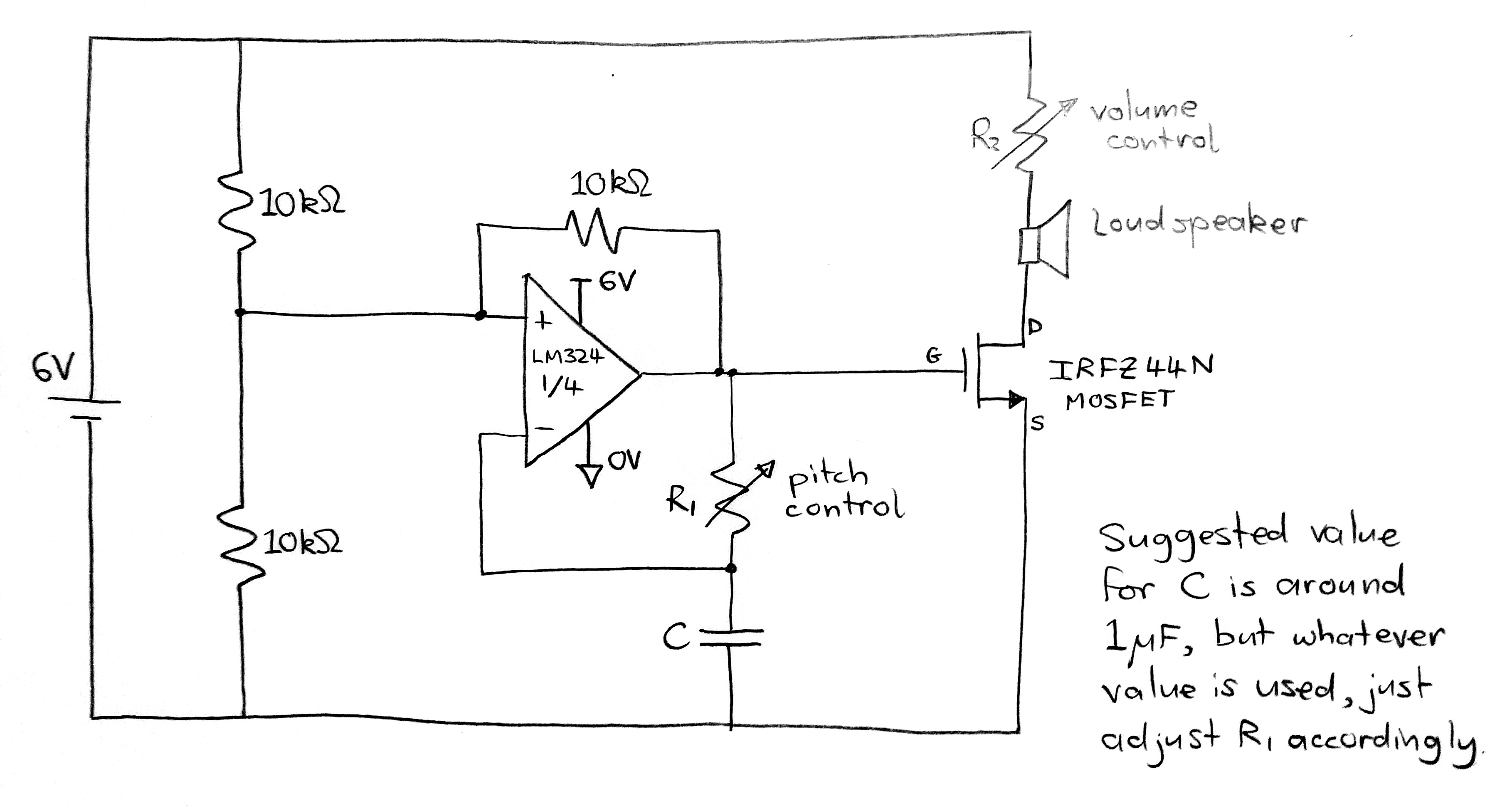
Suggested value for C is 1 µF, but other values can be used.
The second opamp (on the right in the circuit diagram) is used as a unity-gain buffer, which drives the loudspeaker with the square wave output of the oscillator.
To produce a different timbre, try feeding the capacitor voltage signal into the unity gain buffer instead of the square wave.
To play a tune on this synthesizer, connect a long wire to the node at the capacitor terminal and move the wire between the different resistor branches to play a sequence of notes.
This is another analog synthesizer idea, which uses an IRFZ44N MOSFET transistor to drive the loudspeaker.
Vary R1 to control the pitch. With practice, this method can be used to play a tune.
Vary R2 to control the volume. Don’t reduce R2 below about 100 Ω in case you burn out the loudspeaker by driving too much current through it.
In this team project, you will work in a team of three to design and build a small autonomous robot vehicle to compete in a time trial (TT) competition. The robot will have to navigate autonomously along a clearly marked winding track from one end to the other. The project will conclude with a competition in which we measure how long it takes each team’s robot to complete the task. Your team will record a 3-minute video presentation describing the design of your robot.
The project will include the following elements (among others):
Arduino programming
Motor control
Basic mechanical design
Use of one or more TCRT5000 infrared sensors to detect the track
The project grade will be based on three factors:
Performance of your team’s robot in the competition
Quality of your presentation
Tutor observation of your individual contribution to the group work process
Video presentation guidelines:
Each team member must present one minute (60 seconds) of the team video.
Most teams will have three members, but teams with two or four members can adjust the overall video duration so that each team member presents for 60 seconds. (Note: Teams with two members may, if they wish, extend each student’s presentation time to 90 seconds.)
The team should agree in advance what topics each team member will cover.
It’s up to each team member whether they are visible in the video, but every team member must speak out loud in their section of the video. Quality of spoken presentation will be an element in the formal grade.
Quality of visual presentation will be an element in the formal grade.
Your team video must be uploaded to YouTube and set as publicly visible. It can be unlisted. Each team member will confirm that they contributed to the team video by submitting the YouTube link to Brightspace (same link for all team members).
Results will be ranked based on the time taken by each robot to complete the task (as measured by the referee), as well as compliance with the rules set out below.
Competitors are permitted (at the discretion of the referee) to attempt the task multiple times, whether to complete the task for the first time, or to improve upon a previously recorded attempt. Priority may be given to competitors who have not yet recorded a successful attempt.
The track will be a dark stripe on a light-coloured background.
At the beginning of a time trial attempt, the team places their robot over the start end of the stripe. Some part of the robot must be directly above the end of the track when the referee starts the clock.
The robot follows the track from the start to the finish end of the stripe, keeping some part of itself directly above the stripe at all times. Competitors are forbidden from touching or otherwise influencing the robot during the time trial – the robot must be complete the task autonomously.
The clock stops as soon as any part of the robot is directly above the finish end of the stripe. The robot does not need to come to a halt.
If the robot leaves the track at any point (i.e. no part of the robot is directly above the track), that attempt at the time trial is null and void.
The Track
The track will be marked with a clearly visible stripe on a horizontal surface.
The track will be a dark stripe on a light background.
The width of the stripe will be no less than 4cm and no greater than 6cm.
The track consists of five straight sections, each at least 50cm in length.
At every meeting point between two straight sections, the track turns a right-angled corner (i.e. 90 degrees). At each corner, the inner and outer edges of the track will each form a 90 degree angle (i.e. neither edge of the track is rounded at the corner).
As the robot travels along the track from beginning to end, the corners are as follows: left turn, left turn, right turn, right turn.
The recorded result for the time trial will be the time elapsed between the last moment when the robot was above the start end of the stripe and the first moment when the robot is above the finishing end of the stripe.
The robot must remain in contact with the horizontal surface throughout the time trial.
It is not permitted to touch, influence or otherwise interfere with the robot during the time trial – it must operate completely autonomously.
If the robot leaves the track at any point during the time trial, that attempt is null and void. The robot does not need to be in physical contact with the track throughout the attempt, but some part of the robot must always be directly above some part of the track.
Robot specification
The maximum permitted size of the robot is a cube 150 mm on all sides (i.e. 150 mm × 150 mm × 150 mm). At every moment during an attempt, every single part of the robot (including loose wires, etc.) must fit within an upright 150 x 150 x 150 mm cube. Upright means that two sides of the cube are horizontal and four sides are vertical. Note that this size limit is very strictly enforced.
The maximum permitted mass of the robot is 500 g. This weight limit is strictly enforced.
The only permitted power source for the robot is 4 × AA batteries (e.g. the battery pack provided in the RoboSumo kit).
Competitors are permitted to source additional components and materials for use in their robot, at their own expense. However, the maximum permitted budget for parts used in a robot during the time trial is €20 (of the competitors’ own money). This excludes the cost of parts supplied by the college and materials that were obtained for free (provided that similar materials could easily be obtained for free by other competitors). Note that you do not need to spend any money to complete this challenge. Also, please note that any money you choose to spend will not be reimbursed by the college.
Non-compliant robots and late entries
Robots that fail to comply with the above specifications may still be permitted to record a ranked time, at the discretion of the referee. However, their results will be ranked below those of compliant robots that completed the task, irrespective of the time recorded.
Results for teams that complete the task after the end of the formal competition may, at the discretion of the referees, be added to the ranking. However, they will be ranked below teams that completed the challenge during the competition, unless some exceptional circumstances apply (e.g. certified medical absence).
Example TrackTT video
Note that the following video shows a white track on a dark background, but the track used in this project will be a black track on a light-coloured background.
Summary of ranking criteria:
Ranking of results will be according to the following criteria, in order of decreasing precedence:
Robots that are fully compliant with the above robot specification during their ranked attempt will rank above robots that are non-compliant during their ranked attempt.
Robots will be ranked according to the time taken to complete the task. Robots that complete it quicker will be ranked higher.
Referees and conduct of competitors
Every EEPP module lecturer is a competition referee. The module lecturers may also nominate additional referees.
Competitors must follow the referee’s instructions during an attempt.
Competitors who repeatedly fail to follow the referee’s instructions, or who engage in rude or offensive behaviour during the competition may be suspended or disqualified at the discretion of the referee(s).
The referees will aim to treat all competitors fairly. Where a difference of opinion arises, competitors must always respect the decision of the referee. Once the referee makes a decision, competitors must refrain from further argument on the matter.
The referees reserve the right to amend the competition rules or ranking criteria in individual cases, should the need arise (e.g. where a student is absent for medical reasons). Amendments may be applied at the time of the competition or subsequently, which may affect the competition ranking.
At the end of this project, you should be able to:
Solder wires onto the terminals of a motor.
Perform unidirectional speed control of a DC motor using an Arduino and a MOSFET transistor.
Perform bi-directional speed control of a DC motor using an Arduino and an SN754410 driver IC.
Use an oscilloscope to visualise oscillating electrical voltage signals.
There are three items to be submitted to Brightspace for assessment:
A Word document containing the following evidence (additional details below):
Photo of the wires soldered onto your motor.
Photo of your breadboard circuit for Task 1.
Working code for Task 1.
Photo of your breadboard circuit for Task 2.
Working code for Task 2.
A link to a YouTube video showing that Task 1 is complete (details below).
A link to a YouTube video showing that Task 2 is complete (details below).
Project Description
In this project, we explore two ways of controlling a motor with a program running on a microcontroller. In the first task, we use a MOSFET transistor to interface the motor to the Arduino Nano in a way that facilitates unidirectional speed control. In the second task, we use a driver IC to perform bi-directional control of the motor. You will also learn to do some simple soldering.
Task 1: Unidirectional control of a DC motor
The video below provides some background information for this task.
Perform the following steps:
Solder 20 cm long wires onto the terminals of your motor. You can choose whatever wire colour you like, apart from red or black.
Find the datasheet for the IRFZ44N transistor online, so that you can identify which pin is which.
Build the circuit shown in the diagram above on a breadboard. The circuit should be neat and the wires should be appropriately colour-coded. Please pay special attention to correct use of red and black wires.
Program the Arduino to perform the following sequence of LED and motor actions:
LED off and motor driving at 25% duty cycle for 2 seconds.
LED off and motor driving at 50% duty cycle for 2 seconds.
LED off and motor driving at 100% duty cycle for 2 seconds.
LED on and motor stopped for 4 seconds.
Use the oscilloscope to visualise the pulsed signal being emitted from Arduino pin D3. Your lecturer will demonstrate how to do this in the lab.
Record a video showing your circuit performing the above sequence, followed by the oscilloscope displaying the pulsed signal from pin D3 for each state of the system.
Upload the video to YouTube and submit the link to the Brightspace assignment.
Open a new Word document. Insert a heading with your name, student number, the date, the name of this module and the title of this project.
Take a clear photograph of the wires soldered to your motor and add it to the Word document.
Take a clear photograph of your breadboard circuit and add it to your Word document.
Add your working Arduino code for Task 1 to the Word document. Ensure it is neatly formatted and includes clear and accurate comments.
Task 2: Bi-directional control of a DC motor
The videos below provide background information for this task.
Perform the following steps:
Find the datasheet for the SN754410 IC online and use it to identify the correct pin for each connection to the chip. Try googling “SN754410 datasheet” and look for a PDF result.
Build the circuit shown in the diagram above on a breadboard. Note that the final connection between Arduino pin D6 and pin 9 on the SN754410 chip is not shown in the diagram above, but must be included in your circuit to facilitate speed control (as explained in the video). The circuit should be neat and wires should be appropriately colour-coded (please pay special attention to correct use of red and black wires).
Program the Arduino to perform the following sequence of LED and motor actions:
LED off and motor driving forward at 50% duty cycle for 3 seconds.
LED on and motor driving forward at 100% duty cycle for 2 seconds.
LED off and motor stopped for 3 seconds.
LED off and motor driving in reverse at 50% duty cycle for 3 seconds.
LED on and motor driving in reverse at 100% duty cycle for 2 seconds.
LED off and motor stopped for 3 seconds.
Use the oscilloscope to visualise the pulsed signal being emitted from Arduino pin D6.
Record a video showing your circuit performing the above sequence, followed by the oscilloscope displaying the pulsed signal from pin D6 for each state of the system.
Upload the video to YouTube and submit the link to the Brightspace assignment.
Take a clear photograph of your breadboard circuit and add it to your Word document.
Add your working Arduino code for Task 2 to the Word document. Ensure it is neatly formatted and includes clear and accurate comments.
Submit your Word document to the Brightspace assignment.
At the end of this project, you should be able to:
Build a simple breadboard circuit with the Arduino nano microcontroller development board,
Write simple programs to run on the Arduino Nano,
Configure Arduino pins as digital outputs and set their voltages high and low (e.g. to switch LEDs on and off).
Convert between decimal and binary numbers.
There are four items to be submitted to Brightspace for assessment:
Screenshot of the LED Flash Challenge validator web page displaying the congratulations message with your correct team number.
A photo of your breadboard circuit.
The .ino file containing your complete working code. Your code should be neat, correctly indented and clearly commented.
A link to a YouTube video showing all of your team’s circuits working at the same time. You can use your battery pack to power your circuit when it’s plugged out from the PC. One YouTube video for the whole team is sufficient, but every team member should upload the link to the video.
Project Description
This project is a short competitive puzzle called the LED Flash Challenge. In this challenge, doing well means two things: getting it working quickly and, more importantly, trying to understand what you’re doing.
You’ll work in a team to solve this puzzle and complete the challenge, but each member of your team will build and program his/her own Arduino circuit. The challenge consists of two tasks:
Build a simple breadboard circuit for the Arduino Nano and program it to blink a light-emitting diode (LED) on and off.
Add a second LED to the circuit and reprogram the Arduino to transmit your team number as a binary sequence using a series of LED flashes.
The first task is very prescriptive, which means that we’ll basically tell you exactly what to do, but to complete the second task you’ll need to think for yourselves. To complete the second task, you will require a team number – this will be assigned to you by your lecturer.
Task 1: Blinking LED
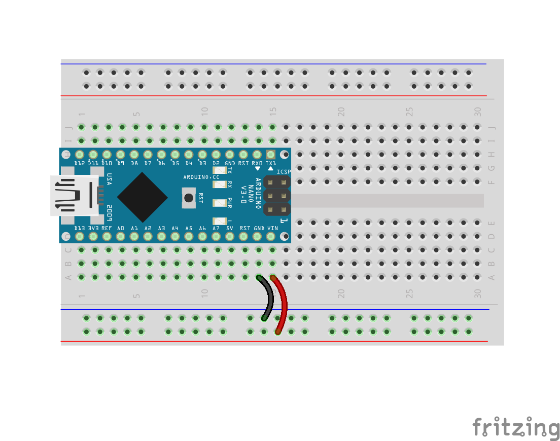
This task is relatively straightforward and shouldn’t take you too long to get working. Before beginning, make sure your breadboard is the same way around as the picture below.
The first component in the circuit is the Arduino Nano, which is a simple computer in a tiny package. In the coming weeks, we will program the Arduino to read signals from different sensors and to control motors and electromagnetic coils. In this project, you will use the Arduino to control some flashing LEDs.
Make sure your Arduino is the right way around, with the mini USB socket at the end of the breadboard (row 1). Place the breadboard flat on a hard surface before pushing the Arduino into the board. The pin marked D12 should be in breadboard hole H1. Some Arduinos can be very difficult to insert into the breadboard, so if you’re having problems just ask for help because you might have just received a particularly tricky one.
As we learned previously, on each side of the breadboard there are two long rows of holes which are connected along the full length of the board. These rails are used to distribute the supply voltage to different parts of the circuit. The blue line marks the negative rail (0V); the red line marks the positive rail (5V in this circuit). The Arduino draws its power from these rails.
Connect a short black wire between A14 and the negative (blue) rail.
Connect a short red wire between A15 and the positive (red) rail.
The first thing we’ll control with the Arduino is a green light-emitting diode (LED). To do this, we’ll turn the Arduino pin marked D2 into a digital output which means that the program running on the Arduino can set it high (5V) or low (0V). When the pin is set high, a small electrical current flows through the green wire, through the green LED, and finally through the resistor to ground (the negative rail).
Insert a green wire between I11 and A18.
Insert a green LED between E18 and E19. The LED is a one-way valve for electricity, so it must be the right way around. Inside the green plastic bead, if you look carefully you’ll see that each leg is connected to a kind of a flat plate. As shown in the image below, the leg connected to the larger plate should be in E19.
Insert a 220 Ω resistor (colour code RED–RED–BROWN–GOLD) with short legs between B19 and the negative (blue) rail.
We’re ready to run a program on the Arduino to flash the green LED on and off.
Double-click the Arduino icon on the desktop to launch the Arduino IDE (integrated development environment).
Delete the example code that appears by default in the editor.
Type the following code into the Arduino IDE editor and save it with the filename “blink”.
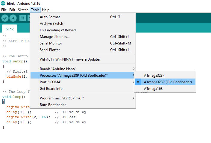
Before running the program on the Arduino Nano, you need to select the correct version of Arduino.
Under the “Tools” menu, enter the “Board” sub-menu and select “Arduino Nano” or “Arduino Nano w/ ATmega328” as shown in the image below.
Under the “Tools” menu, enter the “Processor” sub-menu and select “ATmega328P (Old Bootloader)”.
Under the “Tools” menu, enter the “Port” (or “Serial Port”) sub-menu and select whatever COM device is listed there, as shown below. If the “Port”/”Serial Port” sub-menu is not accessible, please ask your lecturer to check your machine because the Arduino drivers may not be correctly installed.
To download and run the program on the Arduino, click the right-facing arrow button on the toolbar of the Arduino IDE:
At this point you should hopefully see the green LED flashing on and off slowly. If it’s not flashing and you can’t figure out why, please ask your lecturer to check what’s wrong.
Once your LED is blinking, there are four things you need to understand in the code before moving on:
How one of the Arduino pins (D2) was turned into a digital output.
How the LED is turned on.
How the LED is turned off.
How to delay the program for a specified number of milliseconds, so that the rate of the LED blinking can be controlled.
Once you understand these four things, you have finished this part of the task (the easy part) and it’s time to move on to the main part of the LED Flash Challenge.
Task 2:
In this part, you’re going to modify your circuit to create a simple optical transmitter, which transmits a digital message (a sequence of 1s and 0s) as a series of LED flashes.
The message that you’ll transmit will be 2 bytes long (a byte is 8 bits, or 8 ones and zeros) and it will contain your team number (byte 1) followed by a second number, which is calculated by subtracting your team number from 255 (byte 2).
For example, if your team number is 79…
byte1 = 79
byte2 = 255 – 79 = 176
byte1 + byte2 = 255
Here, let me explain how binary numbers work…
Try doing some independent research on binary numbers. You’ll find a lot more great stuff on YouTube, Wikipedia, etc.
Specifically, you need to do the following:
Modify the code to create a second digital output pin.
Extend the circuit by adding a second LED (with current limiting resistor) to that digital output pin.
Convert your team number into an 8-bit binary number. This is byte 1 of your message.
Calculate the required value of byte 2 (so that byte1+byte2 = 255) and write it as an 8-bit binary number.
Each byte will be transmitted as a sequence of ones and zeros, preceded by a start bit (1) and followed by a stop bit (0). That means your complete transmission will be 20 bits long. You should calculate this sequence ad write it down on paper first.
To transmit a 1, turn LED1 off and LED2 on for 500ms.
To transmit a 0, turn LED1 on and LED2 off for 500ms.
To ensure the sequence is received correctly, transmit a long sequence of zeros (for about 5 seconds) before you transmit your message.
As is typically the case in digital transmissions, each byte must be transmitted least significant bit first.
It’s worth repeating point 9 again:
EACH BYTE MUST BE TRANSMITTED LEAST SIGNIFICANT BIT FIRST
Let’s consider that example team number 79 again. As explained above, byte 1 is 79 and byte 2 is 176.
Before transmitting the sequence, send a “0” for about 5 seconds.
The first bit of the sequence is the start bit for byte 1 which is “1”.
Written as a binary number, 79 (seventy-nine) is 0b01001111. The “0b” prefix indicates that a number is being written in binary form – it’s not part of the number value. The byte is transmitted least significant bit first, i.e. in the following order: “1,1,1,1,0,0,1,0”.
The next bit is the stop bit for byte 1, which is “0”.
The next bit is the start bit for byte 2, which is “1”.
Written as a binary number, 216 is 0b10110000, so the next 8 bits are “0,0,0,0,1,1,0,1”.
The final bit is the stop bit for byte 2, which is “0”.
To summarise, the complete 20-bit sequence for team 79 would be as follows:
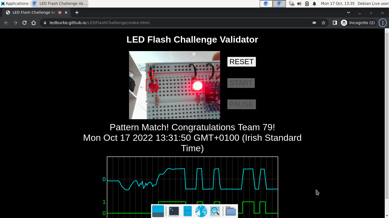
To check your transmission is correct, use the LED Flash Challenge web validator:
When the validator detects a team number, it displays a message similar to that shown below (the team number will vary). Note that the breadboard circuit is held still in front of the camera with one LED in each of the red boxes.
You are welcome to try the validator on your own laptop / PC if it has a camera. It works well in Google Chrome, but should work on most modern web browsers.
Remember to submit the four items of evidence listed at the beginning of this post to Brightspace.
Project type: individual (but feel free to help each other)
Note: You will need to purchase the following for use during EEPP1 labs:
Snips and pliers (available for approximately €5 each from hardware stores, e.g. Lenehans on Capel St or Keys Cut on Mary St).
AA batteries (pack of 12 available for approximately €1.50 from Dealz or Euro General).
In the lab sessions for this module, we undertake a series of projects. Some are individual projects; others are group projects. We begin with an individual project to get you started building and understanding electrical circuits.
At the end of this project, you should be able to:
Understand circuit diagrams,
Identify elements, binary nodes, true nodes and branches in a circuit diagram,
Draw basic circuit diagrams by hand,
Translate a circuit diagram into a neat and fully functioning breadboard circuit,
Find an electronic component’s datasheet online and use it to identify each of its pins/terminals.
Items to be submitted to Brightspace for assessment:
Four evidence photos – one for each of the four circuits shown below.
Component Kit
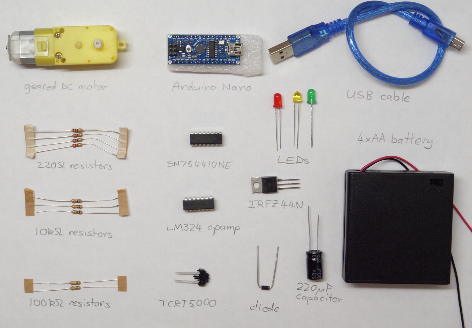
In today’s lab, you will receive a component kit (or part thereof) that you must look after for the duration of the module. You will reuse these components for several projects, so please look after them all carefully. The full kit will contains the following (although you may not receive all components this week):
1 × mini breadboard – This is used to build electrical circuits. It allows us to create electrical connections between components without the need for soldering.
1 × Arduino Nano microcontroller development board
1 × mini USB cable
4 × AA battery pack
1 × geared DC motor
1 × SN754410NE IC
1 × LM324 quad opamp IC
1 × IRFZ44N MOSFET transistor
1 × TCRT5000 infrared reflective sensor
1 × 1N4004 power diode
1 × red LED
1 × green LED
1 × yellow LED
4 × 220 Ω resistor
3 × 10 kΩ resistor
2 × 100 kΩ resistor
1 × 220 μF capacitor
Abbreviations used above:
DC: direct current (as opposed to alternating current)
IC: integrated circuit (another name for a microchip)
The breadboard is shown below. When two wires (or component legs/pins) are plugged into the same short row of five holes, they are electrically connected together by a conducting metal clip that sits under the surface of the board. The rows on each side of the board are numbered from 1 to 30.
On each side of the breadboard, there are two long rails – continuous electrical connections from one end of the board to the other. These rails are marked by the long red and blue lines on the upper surface of the board. Two wires plugged in anywhere on the same rail will be connected together electrically. The rails are typically used to distribute supply voltage around the board without the need for long wires.
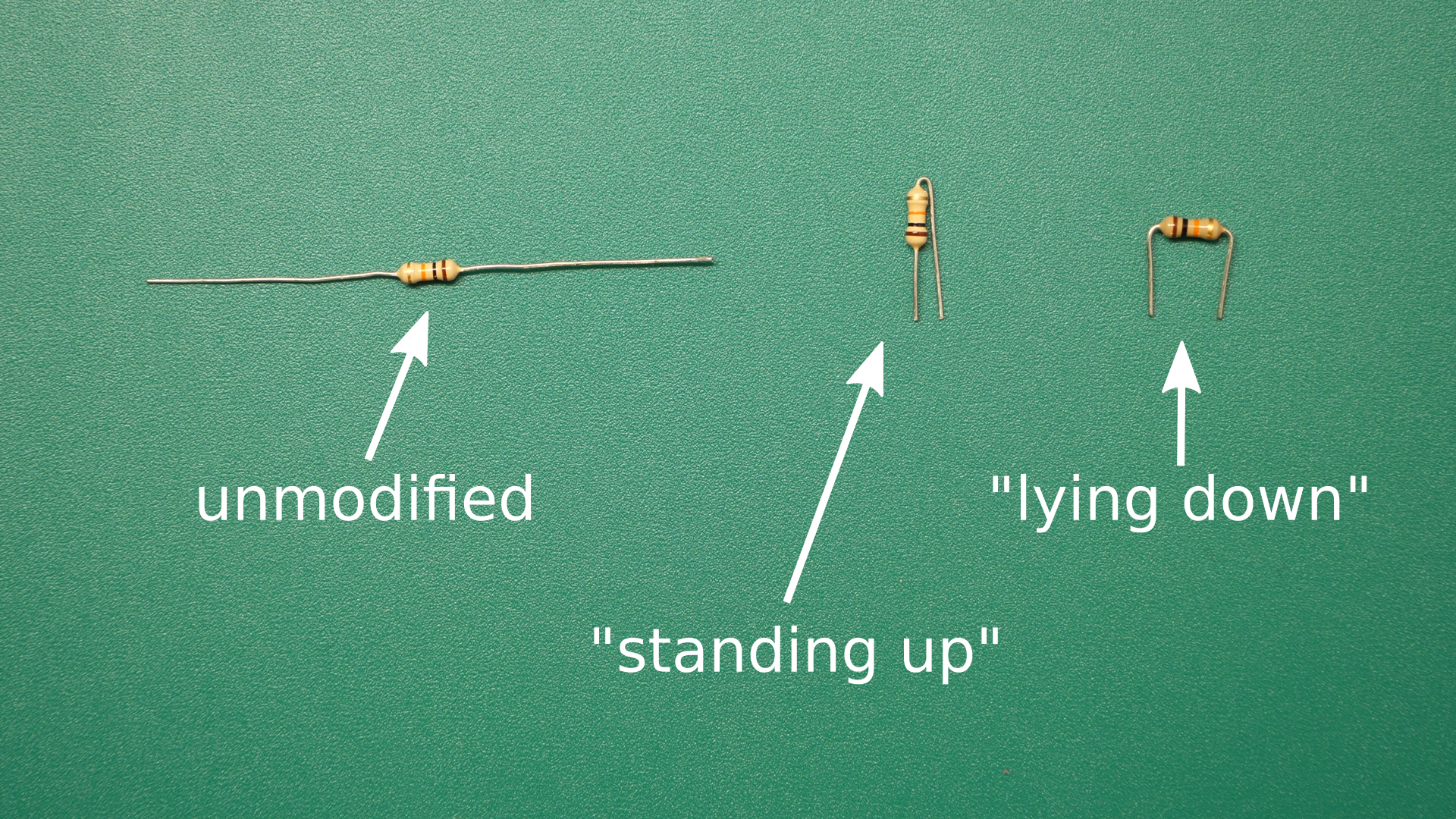
When inserting wires or components into the breadboard, it is desirable to minimise the amount of exposed metal, so that short circuits are less likely to occur. Two neat ways of inserting a resistor into a breadboard are shown below. Connections between different parts of the breadboard can be made with insulated single-core wires.
Colour coding of wires:
Use red wires for nodes in the circuit that are always at the positive supply voltage (e.g. 6 V for the example circuits below). Never use red wire for any other nodes.
Use black wires for nodes in the circuit that are always at the negative supply voltage (normally 0 V). Never use black wire for any other nodes.
Electricity doesn’t care what colour a wire is, but because black and red are universally understood to have the above meanings, it is extremely confusing and potentially dangerous to deviate from that convention.
There are no fixed rules for other wire colours in breadboard circuits, but adopting a logical pattern in your colour coding can be very helpful when troubleshooting.
Additional components and materials will be supplied throughout the module, according to the requirements of each project.
Project Description
Four electrical circuit diagrams are provided below. For each circuit, you will do the following:
Redraw the circuit diagram by hand on a blank (i.e. without lines) sheet of A4 paper.
Write the number of true nodes on the page. Label the true nodes TN0, TN1, TN2, etc.
Write the number of binary nodes on the page. Label the binary nodes BN1, BN2, etc.
Write the number of branches on the page.
Write your name and student number on the page and add a title.
Build the circuit on the breadboard.
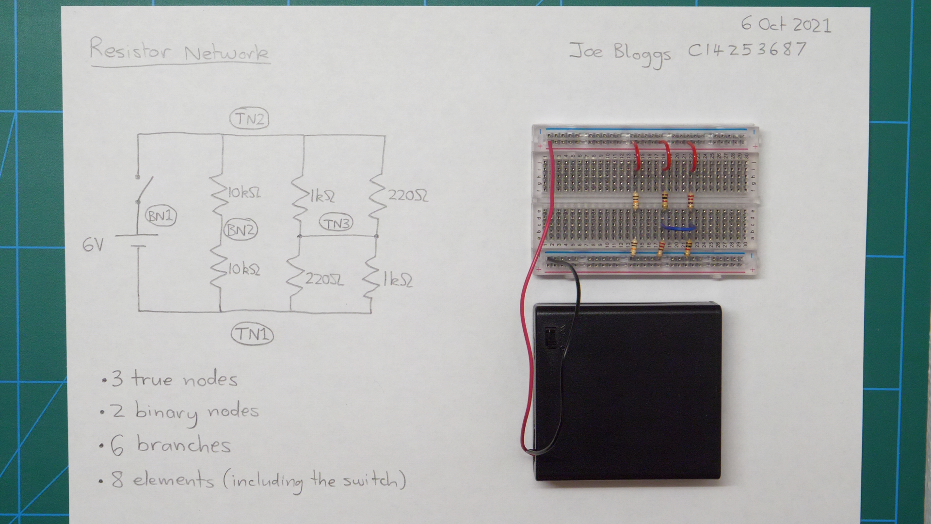
Place the completed breadboard circuit on the page and take a photo showing all of the above items very clearly. An example photo is shown below for an example circuit.
As evidence of your work, submit your photo to the assignment that has been created for this project in the EEPP1 Brightspace module.
The assessment for this project will be based primarily on the (up to) four evidence photos that you submit. Marks will be awarded for each circuit completed (or partially completed). Your mark for each circuit will depend on the technical correctness of your work, as well as the quality of presentation (e.g. clear photograph, neat breadboard circuit, neat circuit diagram, other required information displayed clearly, etc.).
You may not have time to complete all four circuits. That’s okay – we’ll just assess whatever number of circuits you get done. Please upload the evidence photo for each completed circuit before moving on to the next one.
Example circuit: Resistor network
DO NOT BUILD THIS CIRCUIT! It is just provided as an example to show you what kind of photo we want you to submit for each of the circuits below.
If you were provided with this circuit diagram…
…we would want you to submit a photo that looks like this:
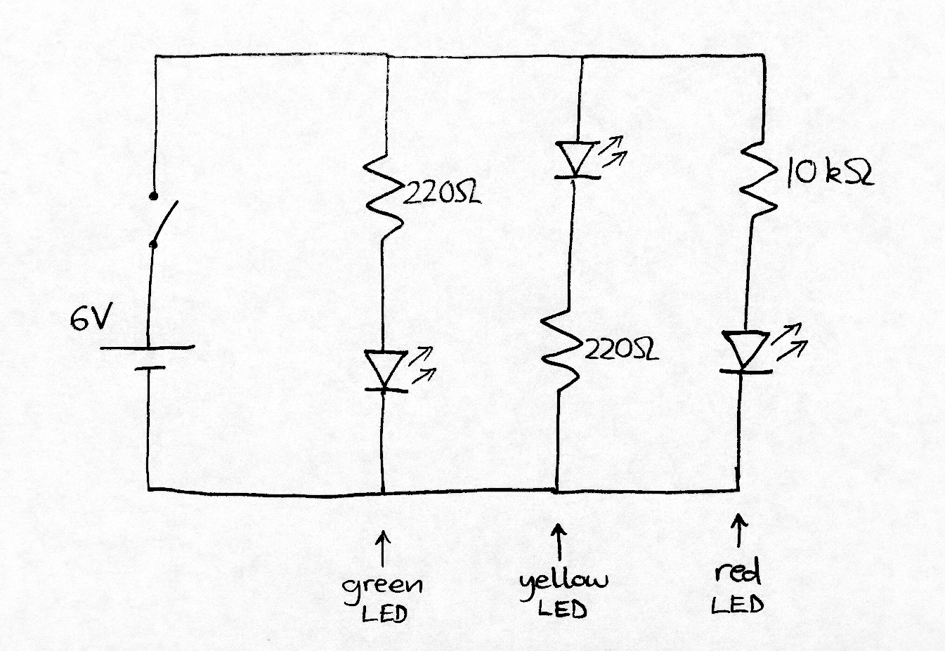
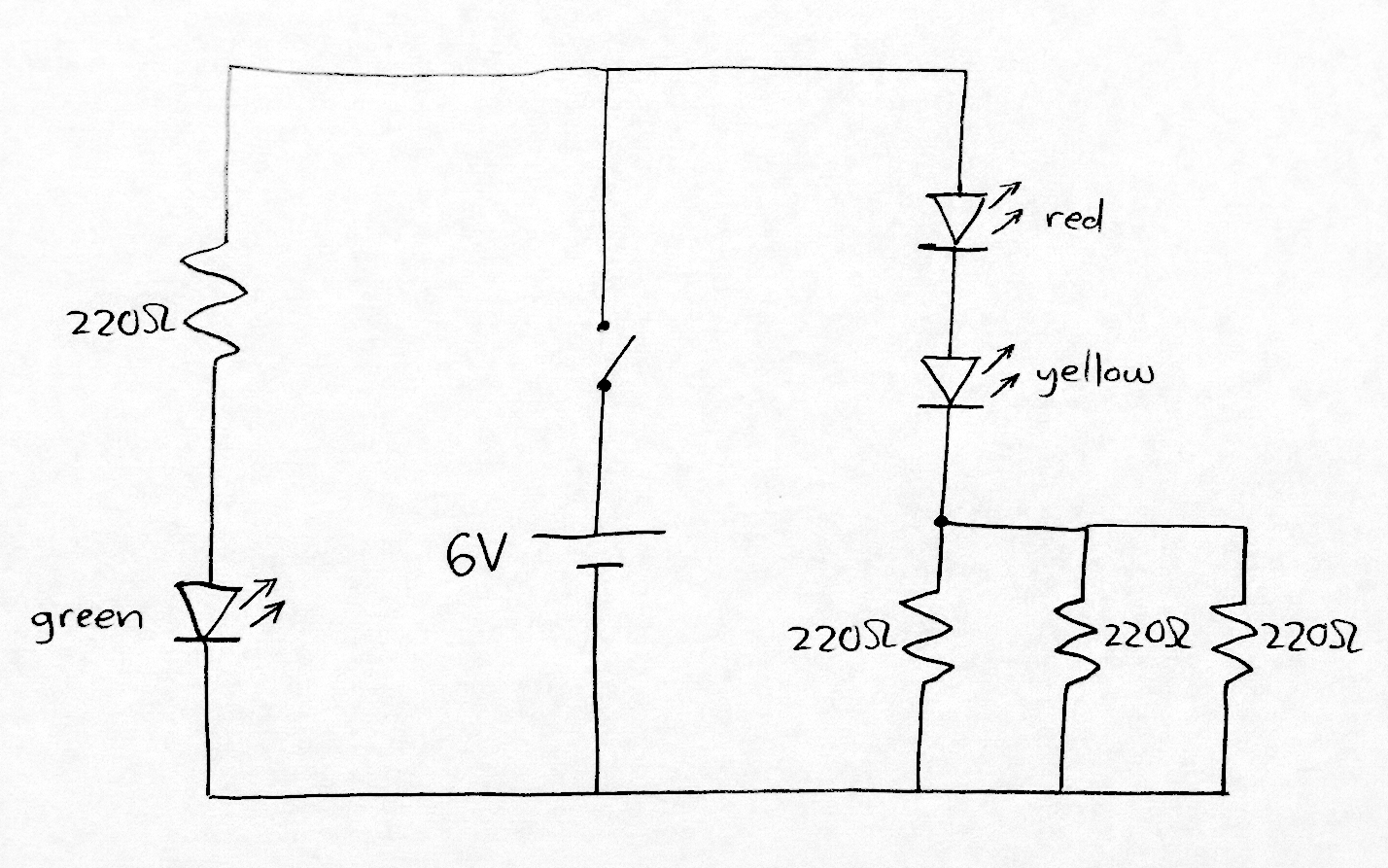
Circuit 1: Three parallel LEDs
This circuit drives current through three LEDs, which should cause them to emit light. However, one of the LEDs in this circuit will be very dim compared to the other two. Can you see why?
Submit a clear photo of your completed breadboard circuit and information page.
Circuit 2: Two LEDs in series
Submit a clear photo of your completed breadboard circuit and information page.
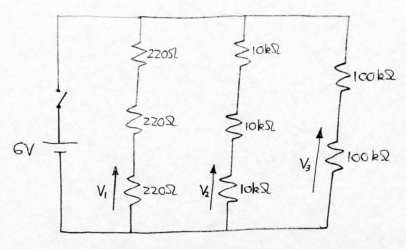
Circuit 3: Resistor ladders
This circuit contains three “resistor ladders” (basically just two or more resistors in series).
In addition to the normal items required on the information page, measure voltages V1, V2 and V3 using a multimeter and write these on the page also. Your lecturer will show you how to use the multimeter (provided one is available in your classroom).
Submit a clear photo of your completed breadboard circuit and information page.
Circuit 4: Infrared proximity sensor circuit
This circuit lights a green LED whenever an object is in close proximity to the TCRT5000 infrared sensor.
To construct this circuit, you will need to download the datasheets for the TCRT5000 infrared sensor and the LM324 opamp IC. A datasheet is a document provided by the manufacturer of a component containing lots of useful information including the pinout, which shows which pins are which. Without the pinout, you won’t know how to connect the TCRT5000 or LM324.
To find the datasheet for any component, just google the name of the component (which is usually written somewhere on the component) together with the word “datasheet” and then look for a PDF result. Your lecturer can help you with this if you’re having trouble finding either of the datasheets you need or making sense of them.
Submit a clear photo of your completed breadboard circuit and information page.
Project duration: 2 weeks Project type: individual (but feel free to help each other)
In this project, you will use pulse width modulation (PWM) to control the brightness of an LED and the angle of a servo motor. You will program the Arduino Nano to control the period and duty cycle (pulse width) of the PWM signals it produces. You will use the oscilloscope to verify that the PWM signals are being produced as expected.
The ATmega328P microcontroller (which the Arduino Nano is based on) provides a vast array of different functionality, including numerous options for producing PWM signals (and related signals). In this project, we program the ATmega328P at the register level to exploit a small part of this functionality. However, we’re really only scratching the surface, so you are strongly encouraged to use this opportunity to begin exploring the ATmega328P datasheet to learn about the many other available options. In particular, try to use the datasheet to make sense of lines of code you don’t understand in the example programs provided below.
To do:
Download the ATmega328P datasheet PDF and explore the chapter entitled “16-bit Timer/Counter1 with PWM”.
What to submit for this project
There are four parts to this project. Each part specifies an evidence item you will need to submit.
The first three evidence items consist of photographs (details below). Please collect all of these in a single Word document. Include your name and student number at the beginning of the Word document.
The fourth evidence item is a video file, which can be uploaded to Brightspace separately.
Only two files should be submitted to Brightspace: the Word document and the video file.
Part 1: Circuit construction
Build the following circuit on your breadboard. Your lab supervisor will provide you with a servo motor. Please note that the servo motor must be returned at the end of the each lab session.
To do:
Build the following circuit on your breadboard.
Take a clear photograph of your breadboard circuit.
EVIDENCE ITEM 1: Add your breadboard photograph to your report document.
Servo motor with 3-pin connector for attaching to breadboard.
Part 2: Control LED brightness
The simplest way to produce PWM signals with the Arduino Nano is using the analogWrite() function from the Arduino library. As explained in the analogWrite documentation, this function can only be used with certain digital i/o pins. When pin D3 outputs PWM (as in the example below), the frequency of the PWM signal is fixed at 490 Hz.
The example below cycles the LED through four different levels of brightness by varying the duty cycle of the PWM signal (0%, 20%, 50% and 100%).
To do:
Upload the following code to the Arduino Nano and verify that the LED brightness is varying as shown in the example video provided below.
Use the oscilloscope to measure the frequency of the PWM waveform.
Using the oscilloscope, take a clear photograph of the PWM waveform during each of the four phases of the sequence.
EVIDENCE ITEM 2: Add the 4 oscilloscope photos to your report document.
//
// Control LED brightness using the Arduino library function analogWrite()
// Written by Ted Burke 25-Apr-2022
//

void setup()
{
  pinMode(3, OUTPUT); // Set pin D3 as an output (same pin as OC2B)
}

void loop()
{
  // Cycle LED through various levels of brightness
  // When using analogWrite() function, pulse widths are from 0 to 255
  analogWrite(3, 0);   // LED not lit (0% PWM duty cycle)
  delay(2000);
  analogWrite(3, 51);  // LED dimly lit (20% PWM duty cycle)
  delay(2000);
  analogWrite(3, 127); // LED brighter (50% PWM duty cycle)
  delay(2000);
  analogWrite(3, 255); // LED at maximum brightness (100% PWM duty cycle)
  delay(2000);
}
Part 3: Servo motor control
The type of servo motor provided to you in this project allows the motor angle to be controlled using a PWM signal. The angle range is between 0 and 180 degrees. The servo has three wires:
BROWN WIRE: ground (0 V)
RED WIRE: positive supply voltage (5 V)
YELLOW WIRE: PWM control signal (switches between 0 V and 5 V)
The PWM control signal has the following properties:
The PWM period is fixed at 20 ms (equivalent to a PWM frequency of 50 Hz, or 50 pulses per second).
Angle is controlled by pulse width.
The pulse width varies between 0.5 ms and 2.5 ms.
0.5 ms corresponds to a servo angle of 0 degrees.
2.5 ms corresponds to a servo angle of 180 degrees.
The following example program outputs PWM from the OC1A pin of the ATmega328P microcontroller (Arduino pin D9). The PWM period is fixed at 20 ms. The pulse width switches between 1.0 ms and 2.0 ms depending on the voltage detected on pin D2, which is controlled using the external switch S1 (or a piece of wire, as shown in the video below).
To do:
Upload the code to the Arduino Nano and verify that the servo angle is changing as expected when the voltage changes on pin D2. The video below illustrates what you should see.
Use the oscilloscope to measure the frequency of the PWM waveform on pin D9.
Use the oscilloscope to capture a clear photograph of the PWM waveform for each of the two servo positions.
EVIDENCE ITEM 3: Add the 2 oscilloscope photos to your report document.
//
// Control of PWM frequency and duty cycle using Arduino Nano / ATmega328P
// Written by Ted Burke 25-Apr-2022
//
// This example uses Timer 1, which is a 16-bit timer
// System clock frequency F_clk = 16 MHz
// Timer 1 prescaler is set to 1/8
// 16-bit register ICR1 controls PWM period (T_pwm = 20 ms)
// 16-bit register OCR1A controls PWM pulse width (i.e. duty cycle)
// PWM output is on pin OC1A (same physical pin as D9)
// Pin OC1B (same pin as D10) is not used in this example
//

void setup()
{
  // Configure Timer 1 for Fast PWM with T_pwm = 20 ms
  // COM2A1:0 = 10  -> Clear OC1A on compare match (set output to low level)
  // COM2B1:0 = 00  -> OC1B disconnected, normal port operation
  // WGM13:0 = 1110 -> Fast PWM wave generation mode with ICR1 controlling period and OCR1A controlling duty cycle
  // CS12:0 = 010   -> Prescaler = 1/8, i.e. set Timer 1 clock to F_clk/8
  TCCR1A = 1<<COM1A1 | 0<<COM1A0 | 0<<COM1B1 | 0<<COM1B0 | 1<<WGM11 | 0<<WGM10;
  TCCR1B = 1<<WGM13 | 1<<WGM12 | 0<<CS12 | 1<<CS11 | 0<<CS10;
  TCNT1 = 0;          // reset Timer 2 counter
  ICR1 = 39999;       // Set PWM period Tpwm = 20 ms, OCR1A = (Tpwm * F_clk * prescaler) - 1
  OCR1A = 3000;       // Set initial PWM pulse width to 1.5 ms, Note: 1000 = 0.5 ms, 5000 = 2.5 ms
  pinMode(9, OUTPUT); // Enable OC1A (same pin as D9) as an output
}

void loop()
{
  if (digitalRead(2) == 1) // switch is closed
  {
    OCR1A = 2000; // pulse width = 1.0 ms, roughly 45 degree angle
  }
  else
  {
    OCR1A = 4000; // pulse width = 2.0 ms, roughly 135 degree angle
  }
}
Part 4: Modify the program to produce a pre-programmed sequence of movements
The video below shows the circuit performing a repeating pre-programmed sequence.
The servo angle increases by 10 degrees every second.
When the servo angle increase, the LED brightness also increases.
When the servo angle reaches 180 degrees, it resets to 0 degrees. The LED brightness also resets to 0.
To do:
Write an Arduino program that reproduces the same pre-programmed sequence.
Record the video of your circuit performing the sequence.
EVIDENCE ITEM 4: Submit the video of your circuit reproducing the specified sequence of movements to Brightspace.
You may find the following helper function useful. It allows the servo to be moved to a specified angle (in degrees) with a single function call.
void set_angle(float angle)
{
  // Pulse width variables
  float pw;              // pulse width
  float pw_min = 0.5e-3; // minimum pulse width is 0.5 ms, which sets angle to 0 degrees
  float pw_max = 2.5e-3; // maximum pulse width is 2.5 ms, which sets angle to 180 degrees

  // Calculate pulse width and then use it to update OCR1A
  pw = pw_min + (angle/180.0) * (pw_max-pw_min);
  OCR1A = pw * 16e6 / 8;
}
Project type: individual (but feel free to help each other)
The objective in this project is to decode a secret 4-character message that has been encoded as an optical binary signal in the form of a flashing region in a video. Each of you has been assigned a unique 4-character code. You will build a simple optical detector circuit that can be used to record the binary signal and display it on the oscilloscope so that you can decode the secret message.
Each character is encoded as a single byte (8 bits) using the ASCII system.
Each byte is transmitted least significant bit (lsb) first.
Each byte is preceded by a start bit (equal to 1).
Each byte is followed by a stop bit (equal to 0).
Bits equal to “1” are represented by white in the video.
Bits equal to “0” are represented by black in the video.
The following example signal encodes the word “Demo”:
Instructions
Build a photodetector circuit (two options are provided below – version 2 is recommended).
Use an oscilloscope to check that the output voltage of the photodetector changes when the intensity of light falling on the LED(s) changes.
Identify the flashing region labelled with your initials in the binary signal video.
Hold the LED(s) up to that part of the screen and use the oscilloscope to record the binary waveform. Once you have the complete 4-byte transmission displayed on the oscilloscope screen, press pause so that you can photograph it and decode the signal.
Once you’ve figured out your individual 4-character secret message, check with your lab supervisor to see if you got it right.
ADVANCED CHALLENGE: If you complete all previous parts, try programming the Arduino to automatically decode this type of binary signal and print the 4-character code word in the Serial Monitor. Feel free to collaborate with your classmates on this part.
Submit a 1-page Word document to Brightspace containing the following:
Your name.
Your individual 4-character secret message.
A photograph of your photodetector circuit.
A photograph of your complete 4-byte binary transmission displayed on the oscilloscope screen.
OPTIONAL: If you attempted the advanced challenge, include evidence of whatever you did in the Word document.
Photodetector circuit
Two photodetector circuits are provided below. The first is simpler and easier to understand, but the second one works much better. You are advised to use the second one for this challenge.
Version 1 : Simple but flawed
Minimal design.
Easy to build and understand.
Works, but not very well.
The reverse-biased LED acts as a photodiode. When light strikes it, a tiny reverse current is allowed to pass through it. The more intense the light, the larger the current (although it’s always very small).
The NPN bipolar junction transistor (BJT) acts as a current amplifier. The tiny base current arriving from the LED controls a much larger collector current, which passes through the resistor R.
The voltage across resistor R varies with the magnitude of the collector current, and hence with the intensity of light falling on the LED.
Photodetector version 1
Version 2 : Much improved output signal
Same principle of operation as the previous circuit.
The addition of a second LED results in twice as much current for the same light intensity.
The two transistors are connected as a Darlington pair, which results in an overall current gain that is approximately equal to the product of the individual transistors’ current gains.
This circuit produces a much clearer voltage output signal than the other version of the circuit.
A smaller resistor can be used because the increased current gain results in a larger collector current. Reducing the resistance allows the output voltage to respond faster to changes in light intensity.
Photodetector version 2
Alternative method using Arduino instead of oscilloscope
To complete the binary signal detective challenge without an oscilloscope, the Arduino Nano and Serial Plotter can be used to visualise the binary waveform output from the photodetector circuit. Just upload the following code to the Arduino and then connect the output of the photodetector circuit to pin A0.
Open the Serial Plotter (under the Tools menu in the Arduino development environment) and you should see a waveform resembling the one below when you hold your LED photodetectors up to the flashing signal on the screen.
Project duration: 2 weeks practical work + 1 week video production
Project type: group (3 per group)
In this project, you will work in teams to solve a very practical electrical engineering problem using the theory and tools we have been learning about for the last couple of weeks (e.g. phasors, impedance, MATLAB/Octave, LTspice). This project is designed to force you to do independent research on the topic of power in AC circuits and especially power factor correction.
The problem you need to solve is described below. Begin by discussing the problem description with your team and identifying knowledge gaps you need to fill. Then go and learn whatever you need to learn to solve the problem. Finally, present your solution in a group video presentation that will be uploaded to YouTube. We will screen all the videos together in class in the final lab session of the project.
Problem Description
On an island far from the mainland, a small power station (i.e. a voltage source) supplies 50 Hz AC power to a remote water pumping station via a long single-phase (i.e. 2 conductor) overhead power line. The power line cable is solid aluminium with a circular cross section. The pumping station can be modeled as a resistance in series with an inductance. The inductance and capacitance of the power line can be ignored, as can skin effect. However, the resistance of the power line will be significant, so it must be taken into account. Your first task is to analyse the power factor of the load (the pumping station) and calculate the losses in the power line. Your second task is to design a power factor correction solution for the pumping station and calculate the reduction in power line losses. Finally, you will present your work in a group video presentation.
The following information will be provided to your team (different values for each team):
VS : the r.m.s. voltage supplied by the power station
Rload : equivalent resistance of the pumping station
Lload : equivalent inductance of the pumping station
d : distance from the power station to the pumping station
D : diameter of the aluminium power line cable
Once your lab instructor assigns a number to your team, select your values from the list below.
Derek / Ted’s teams:
Team 1: VS =400 V r.m.s., Rload = 7.12 Ω, Lload = 12.9 mH, d = 2.5 km, D = 8.0 mm
Team 2: VS =380 V r.m.s., Rload = 7.42 Ω, Lload = 13.9 mH, d = 2.4 km, D = 7.0 mm
Team 3: VS =400 V r.m.s., Rload = 7.62 Ω, Lload = 12.9 mH, d = 2.6 km, D = 7.2 mm
Team 4: VS =380 V r.m.s., Rload = 7.02 Ω, Lload = 13.9 mH, d = 2.5 km, D = 7.8 mm
Kevin’s teams:
Team 5: VS =400 V r.m.s., Rload = 7.52 Ω, Lload = 13.9 mH, d = 2.6 km, D = 8.0 mm
Team 6: VS =380 V r.m.s., Rload = 7.22 Ω, Lload = 12.9 mH, d = 2.5 km, D = 7.0 mm
Team 7: VS =400 V r.m.s., Rload = 7.02 Ω, Lload = 13.9 mH, d = 2.4 km, D = 7.2 mm
Team 8: VS =380 V r.m.s., Rload = 7.32 Ω, Lload = 12.9 mH, d = 2.6 km, D = 7.8 mm
Suggested calculations
You will find it useful to calculate the values listed below. You may need to carry out some independent research to learn what some of these are.
Power factor of the RL load, cos(ϕ),
Load voltage phasor Vload and load current phasor Iload,
Complex, active, reactive and apparent power in the load (S, P, Q, and |S| respectively) before and after power factor correction,
The active power dissipated in the power line (Pline).
The following page summarises a lot of relevant background information:
In today’s lab sessions, we are learning how to use Octave/MATLAB and LTspice for AC circuit analysis and simulation. The following video reviews some basic theory, then shows a complete worked example for an AC circuit similar to (but not the same as) the one you will be investigating. First, a phasor analysis is demonstrated in Octave. Then the circuit is simulated in LTspice. Finally, the results of the phasor analysis and simulation are compared.
You will be analysing and simulating a different circuit, which is shown below:
Vs is a sinusoidal AC voltage source, with magnitude 230 V r.m.s. and a frequency of 50 Hz.
R1 = 10 kΩ
R2 = 10 kΩ
R3 = 10 Ω
L = 20 mH
C = 220 μF
Part 1: Octave / MATLAB analysis
(Submit your finished M-file to Brightspace as evidence, together with a screenshot of the calculated values displayed in the command window of Octave/MATLAB)
Using Octave or MATLAB, carry out a phasor analysis of the currents and voltages in the circuit. Make Vs the reference phasor (i.e. just set Vs equal to the r.m.s. magnitude of supply voltage so that it has zero phase angle).
Calculate the phasor current in R2.
Calculate the phasor voltage across R2.
Calculate the peak voltage across R2.
Calculate the phasor current in C.
Calculate Vc, the phasor voltage across C.
Calculate the peak voltage across C.
What is the phase angle of Vc? Is it leading or lagging Vs?
Submit your finished M-file to Brightspace, including clear comments identifying each step in the process (similar to the example shown in the video above). Also submit a screenshot of your M-file running the Octave/MATLAB command window, with all seven values listed above clearly displayed.
Part 2: LTspice simulation
(Submit the two LTspice screenshots described below to Brightspace as evidence)
Simulate the circuit (same circuit as part 1) in LTspice. As evidence of your successful simulation, obtain the two LTspice screenshots described below:
Screenshot 1:
Display the circuit schematic in one pane.
In a second pane, display a plot of exactly two cycles (i.e. 40 ms) of the oscillating supply voltage and the voltage across resistor R2. Choose a time period when both waveforms are at steady state (i.e. not at the very start of the simulation).
No other traces (waveforms) should be displayed on the plot.
Add a text label to each of the two traces to identify which is which.
Using the two cursors in LTspice, clearly mark the peak supply voltage and the peak voltage across R2.
Screenshot 2:
Display the circuit schematic in one pane.
In a second pane, display a plot showing exactly 4 cycles of the following three traces: the supply voltage, the voltage across capacitor C and the current through capacitor C.
Using the two cursors in LTspice, mark the peak of the supply voltage and the nearest peak of the capacitor voltage. Hence measure the time difference between the waveforms and calculate the equivalent phase shift between them.
Add two text labels to the plot – one stating the phase difference predicted by the earlier phasor analysis (the angle of phasor Vc), and the other stating the phase difference calculated by measuring the time shift between the waveforms in the LTspice plot. The two should agree – do they?
The objective of this project is to construct a parallel plate capacitor from readily available materials such as aluminium foil (for the conducting plates) and paper (for the dielectric that separates the plates). You’re free to improvise with other materials, but please observe the following rules:
Use only dry materials in your capacitor. No liquids!
Carefully assess any potential risks associated with the materials you’re using and avoid doing anything that might cause injury (e.g. cutting up aluminium cans which produces dangerously sharp edges).
You’re encouraged to try to make the capacitance large. However, we’re also interested in how densely you can cram the capacitance into a compact space. Even better would be if your capacitance is variable. We’re hoping that some of you will impress us with creative solutions.
To give you time to develop something impressive, we’ll spend two weeks (i.e. 10 laboratory hours) on the practical phase of the project. Both lab sessions in the third week of the project will be spent writing a technical report on your work, under the supervision of your lab tutor. The following example report (for a different, but related experiment) is provided to guide you in writing your own report:
The following equation gives the expected capacitance for an ideal parallel plate capacitor.
where
C is the capacitance in farads [F],
is the absolute permittivity (often just referred to as the permittivity) of the dielectric (insulating material) that separates the conducting plates in farads per meter [Fm-1],
A is the area of each plate in square metres [m2], and
d is the distance between the plates in metres [m].
Note that the dielectric thickness, d, shown in the above diagram is greatly exaggerated. In a real capacitor, the dielectric would typically be extremely thin in order to get the plates as close to each other as possible.
Permittivity is a property of a material or medium in which an electric field is present. Tables of permittivity values are available for different materials (e.g. air, water, concrete, soil, glass, etc.). Permittivity has a very significant effect on how electromagnetic waves propagate through a medium so, among other things, it can tell us useful information about how mobile phone or wi-fi signals will penetrate the walls of a building. The medium with the lowest possible permittivity is a perfect vacuum. The permittivity of a material is often stated as a relative permittivity – the ratio between its absolute permittivity and the absolute permittivity of a vacuum.
where
is the absolute permittivity of the material in question in farads per metre [Fm-1],
is the relative permittivity of the material, which is a dimensionless value (i.e. it has no units because it’s the ratio of two values that have the same units), and
is the permittivity of a vacuum, 8.854188 ✕ 10-12 farads per metre [Fm-1].
The permittivity of air is very close to that of a vacuum, so it has a relative permittivity of approximately 1. Materials that are good insulators tend to have low relative permittivities. Have a look online for some of the published lists of material permittivities.
Part 1: Construct a simple parallel plate capacitor
To begin with, construct a simple capacitor as follows:
Cut out two square pieces of aluminium foil, approximately 20 cm x 20 cm, but leaving an extra strip of foil extending from one corner of each piece (for attaching wires).
Cut two long wires – long enough to reach from the breadboard to opposite corners of your 20 cm x 20 cm square capacitor. Remove the insulation from the last 2 cm of each wire.
Sellotape one wire onto the corner strip of each piece of foil.
Lay one piece of foil down smooth flat surface.
Lay a piece of A4 paper on top of the foil, taking care to cover every part of it except for the strip with the wire attached.
Lay the second piece of foil down so that it is directly above the first piece (but separated from it by the paper). Orient it so that the corner with the wire attached is not at the same corner as the wire for the lower plate.
Lay something flat and heavy (like a hardback book) on top to press the three layers tightly together.
To measure the capacitance of your capacitor, plug the wires into a breadboard and build an RC circuit by connecting it to a resistor (e.g. 100 kΩ) and signal generator. Using the oscilloscope, measure the time constant of the RC circuit and hence estimate the capacitance. (To give you a rough idea what to expect, when I tried building this capacitor I obtained a capacitance of approximately 15 nF.)
Try pressing down hard on the stack to squeeze the plates ever closer together. Does it affect the measured capacitance? Can you see the time constant changing?
Using the equation from the theory section above, estimate the expected capacitance of this capacitor and compare it to the measured value. When applying the formula, note the following:
The area of the plates must be expressed in square metres.
The distance between the plates should be approximately equal to the thickness of the paper sheet. This is difficult to measure directly, but if you measure the height of a stack of sheets then divide by the number of sheets, a reasonably accurate estimate can be obtained. This distance must be expressed in metres.
Different types of paper will have different relative permittivities. The exact value for the paper you’re using won’t be possible to find, but you should be able to find a reasonable ballpark estimate online.
Retain all your calculations, measurements, and links to information sources so that you can include them all in your lab report next week.
Part 2: Design, build and test a larger and/or variable capacitor
Now you’re ready to create your own capacitor design, hopefully with a larger capacitance than the simple design described above. If you can think of a way to make the capacitance variable, that would be a major bonus.
Strategies to consider:
Increase the area of the plates?
Try a thinner dielectric material?
Use a dielectric with a different permittivity?
Stack more plates together?
Roll your capacitor into tightly rolled cylinder?
Create more than one capacitor and combine them in parallel?
Vary the capacitance by sliding one plate over the other?
Vary the capacitance by squashing the plates closer together?
Research online to get some more ideas.
To prepare for writing your report, please retain or collect all of the following items:
Photographs of everything you built, ideally including steps during the build process.
Screenshots of anything you measured using the oscilloscope.
Any calculations you carried out. If the calculations were carried out on paper, then retain the written calculations. If the calculations were carried out in MATLAB / Octave, then grab a screenshot or save it to an M-file so that you can refer back to it.
The sources of any information you obtained online – e.g. material permittivity, thickness of paper / cling film, etc.
Part 2b (optional): Variable frequency oscillator
Try incorporating your variable capacitor into the oscillator circuit you built in the synthesizer project at the end of semester 1, so that you can vary the frequency of oscillation.
Part 3: Write a lab report about the capacitor you built (during labs in week 3 of project)
An example lab report is provided to guide your writing. The example report is for a different, but closely related, experiment. Use it as a template for writing your report about this project.
Submit one report per group – i.e. a single Word document / PDF.
Identify all team members clearly at the start of the report.
Each team member writes at least one full section.
Proofread each others sections of the report to identify errors.
Clearly label the author(s) of each section of the report. The name(s) can be included in brackets following each section title.


 is the absolute permittivity (often just referred to as the permittivity) of the dielectric (insulating material) that separates the conducting plates in farads per meter [Fm-1],

 is the relative permittivity of the material, which is a dimensionless value (i.e. it has no units because it’s the ratio of two values that have the same units), and
 is the permittivity of a vacuum, 8.854188 ✕ 10-12 farads per metre [Fm-1].

