Expected project duration: 1 week (i.e. 2 lab sessions)
In the lab sessions for this module, we undertake a series of projects. Some are individual projects; others are group projects. We begin with an individual project to get you started building and understanding electrical circuits.
At the end of this project, you should be able to:
- Understand circuit diagrams,
- Identify elements, binary nodes, true nodes and branches in a circuit diagram,
- Draw basic circuit diagrams by hand,
- Translate a circuit diagram into a neat and fully functioning breadboard circuit,
- Find an electronic component’s datasheet online and use it to identify each of its pins/terminals.
Items to be submitted to Brightspace for assessment:
- Four evidence photos – one for each of the four circuits shown below.
Component Kit
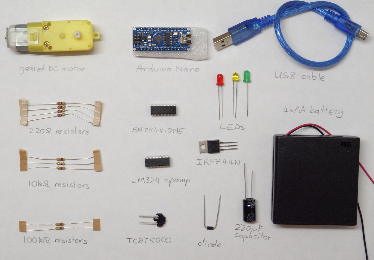
In today’s lab, you will receive a component kit that you must look after for the duration of the module. You will reuse these components for several projects, so please look after them all carefully. The kit contains:
- 1 × mini breadboard – This is used to build electrical circuits. It allows us to create electrical connections between components without the need for soldering.
- 1 × Arduino Nano microcontroller development board
- 1 × mini USB cable
- 4 × AA battery pack
- 1 × geared DC motor
- 1 × SN754410NE IC
- 1 × LM324 quad opamp IC
- 1 × IRFZ44N MOSFET transistor
- 1 × TCRT5000 infrared reflective sensor
- 1 × 1N4004 power diode
- 1 × red LED
- 1 × green LED
- 1 × yellow LED
- 4 × 220 Ω resistor
- 3 × 10 kΩ resistor
- 2 × 100 kΩ resistor
- 1 × 220 μF capacitor
Abbreviations used above:
- DC: direct current (as opposed to alternating current)
- IC: integrated circuit (another name for a microchip)
- LED: light-emitting diode
- MOSFET: metal-oxide-semiconductor field-effect transistor
- opamp: operational amplifier
The breadboard is shown below. When two wires (or component legs/pins) are plugged into the same short row of five holes, they are electrically connected together by a conducting metal clip that sits under the surface of the board. The rows on each side of the board are numbered from 1 to 30.
On each side of the breadboard, there are two long rails – continuous electrical connections from one end of the board to the other. These rails are marked by the long red and blue lines on the upper surface of the board. Two wires plugged in anywhere on the same rail will be connected together electrically. The rails are typically used to distribute supply voltage around the board without the need for long wires.
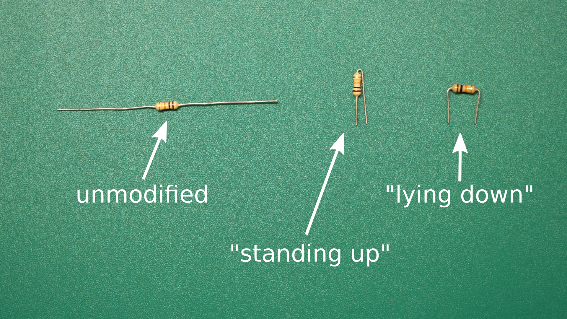
When inserting wires or components into the breadboard, it is desirable to minimise the amount of exposed metal, so that short circuits are less likely to occur. Two neat ways of inserting a resistor into a breadboard are shown below. Connections between different parts of the breadboard can be made with insulated single-core wires.

Colour coding of wires:
- Use red wires for nodes in the circuit that are always at the positive supply voltage (e.g. 6 V for the example circuits below). Never use red wire for any other nodes.
- Use black wires for nodes in the circuit that are always at the negative supply voltage (normally 0 V). Never use black wire for any other nodes.
- Electricity doesn’t care what colour a wire is, but because black and red are universally understood to have the above meanings, it is extremely confusing and potentially dangerous to deviate from that convention.
- There are no fixed rules for other wire colours in breadboard circuits, but adopting a logical pattern in your colour coding can be very helpful when troubleshooting.
Additional components and materials will be supplied throughout the module, according to the requirements of each project.
Project Description
Four electrical circuit diagrams are provided below. For each circuit, you will do the following:
- Redraw the circuit diagram by hand on a blank (i.e. without lines) sheet of A4 paper.
- Write the number of true nodes on the page. Label the true nodes TN0, TN1, TN2, etc.
- Write the number of binary nodes on the page. Label the binary nodes BN1, BN2, etc.
- Write the number of branches on the page.
- Write your name and student number on the page and add a title.
- Build the circuit on the breadboard.
- Place the completed breadboard circuit on the page and take a photo showing all of the above items very clearly. An example photo is shown below for an example circuit.
- As evidence of your work, submit your photo to the assignment that has been created for this project in the EEPP1 Brightspace module.
The assessment for this project will be based primarily on the (up to) four evidence photos that you submit. Marks will be awarded for each circuit completed (or partially completed). Your mark for each circuit will depend on the technical correctness of your work, as well as the quality of presentation (e.g. clear photograph, neat breadboard circuit, neat circuit diagram, other required information displayed clearly, etc.).
You may not have time to complete all four circuits. That’s okay – we’ll just assess whatever number of circuits you get done. Please upload the evidence photo for each completed circuit before moving on to the next one.
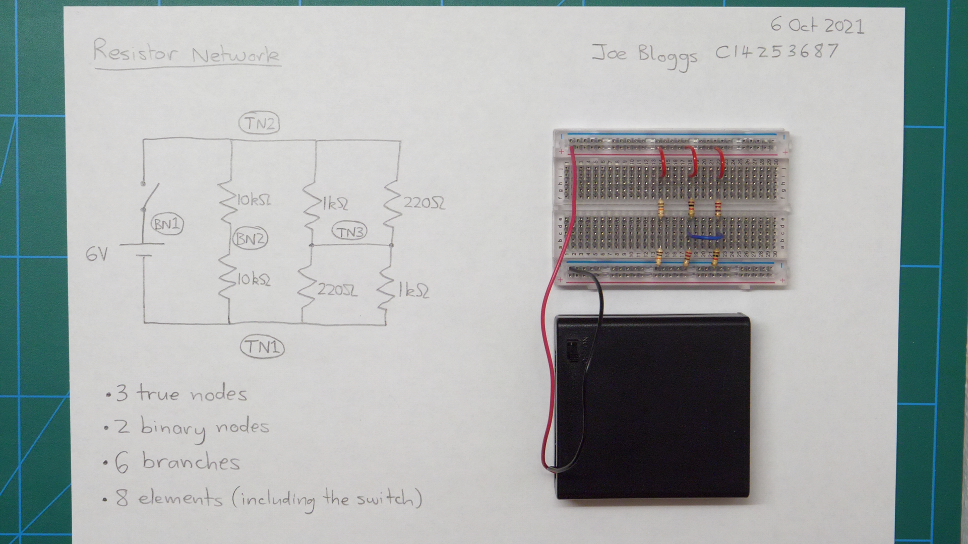
Example circuit: Resistor network
DO NOT BUILD THIS CIRCUIT! It is just provided as an example to show you what kind of photo we want you to submit for each of the circuits below.
If you were provided with this circuit diagram…

…we would want you to submit a photo that looks like this:
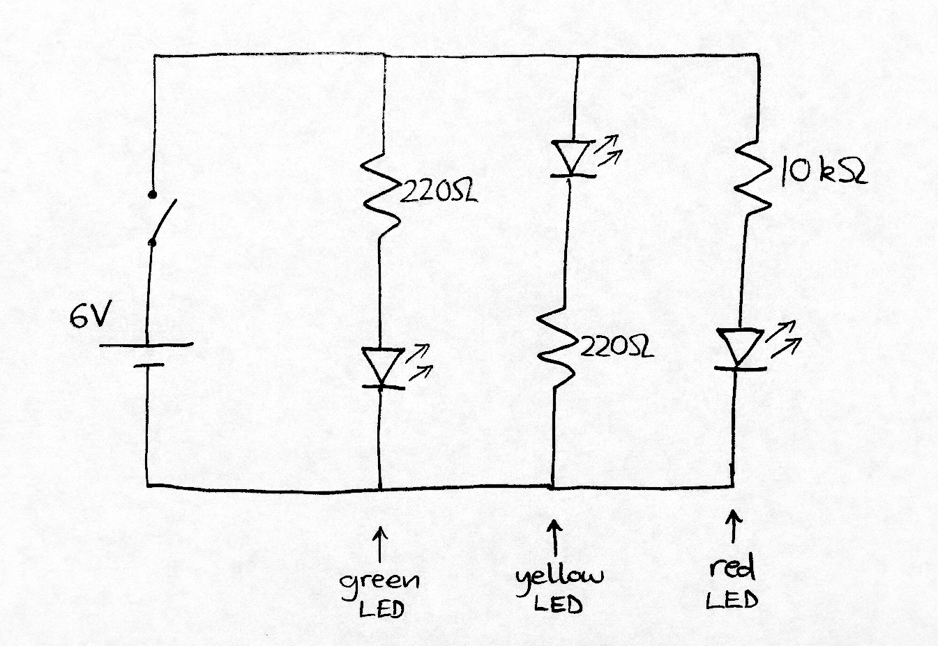
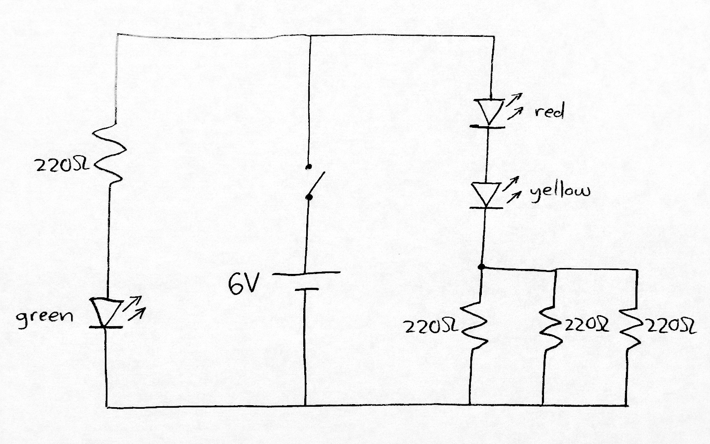
Circuit 1: Three parallel LEDs
This circuit drives current through three LEDs, which should cause them to emit light. However, one of the LEDs in this circuit will be very dim compared to the other two. Can you see why?
Submit a clear photo of your completed breadboard circuit and information page.
Circuit 2: Two LEDs in series
Submit a clear photo of your completed breadboard circuit and information page.
Circuit 3: Resistor ladders
This circuit contains three “resistor ladders” (basically just two or more resistors in series).
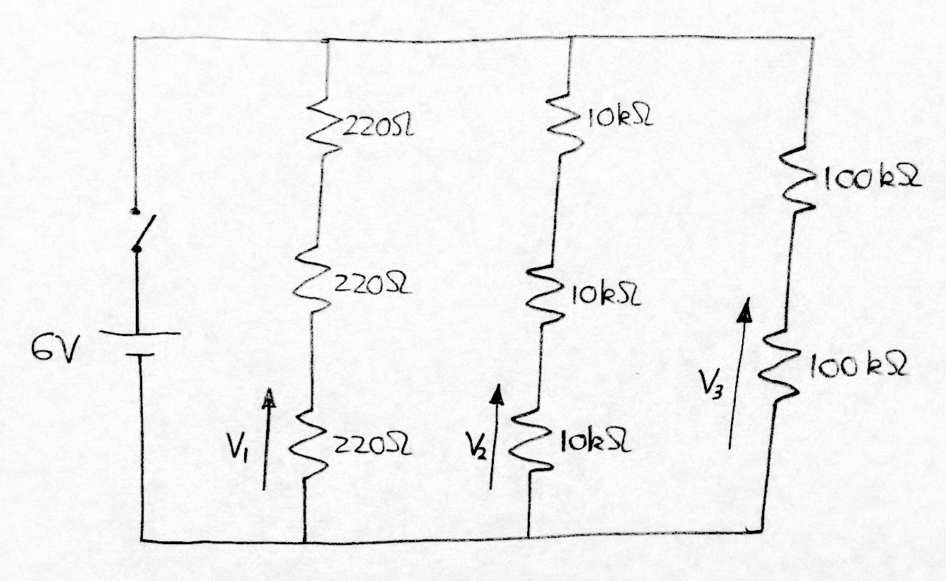
In addition to the normal items required on the information page, measure voltages V1, V2 and V3 using a multimeter and write these on the page also. Your lecturer will show you how to use the multimeter (provided one is available in your classroom).
Submit a clear photo of your completed breadboard circuit and information page.
Circuit 4: Infrared proximity sensor circuit
This circuit lights a green LED whenever an object is in close proximity to the TCRT5000 infrared sensor.

To construct this circuit, you will need to download the datasheets for the TCRT5000 infrared sensor and the LM324 opamp IC. A datasheet is a document provided by the manufacturer of a component containing lots of useful information including the pinout, which shows which pins are which. Without the pinout, you won’t know how to connect the TCRT5000 or LM324.
To find the datasheet for any component, just google the name of the component (which is usually written somewhere on the component) together with the word “datasheet” and then look for a PDF result. Your lecturer can help you with this if you’re having trouble finding either of the datasheets you need or making sense of them.
Submit a clear photo of your completed breadboard circuit and information page.
