2021-22 Sem 2 Project 5: Binary Signal Detective

Project duration: 1 week

Project type: individual (but feel free to help each other)

The objective in this project is to decode a secret 4-character message that has been encoded as an optical binary signal in the form of a flashing region in a video. Each of you has been assigned a unique 4-character code. You will build a simple optical detector circuit that can be used to record the binary signal and display it on the oscilloscope so that you can decode the secret message.

Alternative link to download video file

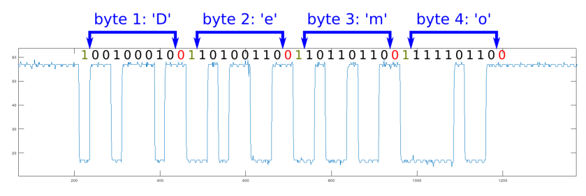
  • Each character is encoded as a single byte (8 bits) using the ASCII system.
  • Each byte is transmitted least significant bit (lsb) first.
  • Each byte is preceded by a start bit (equal to 1).
  • Each byte is followed by a stop bit (equal to 0).
  • Bits equal to “1” are represented by white in the video.
  • Bits equal to “0” are represented by black in the video.

The following example signal encodes the word “Demo”:
Instructions

  1. Build a photodetector circuit (two options are provided below – version 2 is recommended).
  2. Use an oscilloscope to check that the output voltage of the photodetector changes when the intensity of light falling on the LED(s) changes.
  3. Identify the flashing region labelled with your initials in the binary signal video.
  4. Hold the LED(s) up to that part of the screen and use the oscilloscope to record the binary waveform. Once you have the complete 4-byte transmission displayed on the oscilloscope screen, press pause so that you can photograph it and decode the signal.
  5. Once you’ve figured out your individual 4-character secret message, check with your lab supervisor to see if you got it right.
  6. ADVANCED CHALLENGE: If you complete all previous parts, try programming the Arduino to automatically decode this type of binary signal and print the 4-character code word in the Serial Monitor. Feel free to collaborate with your classmates on this part.

Submit a 1-page Word document to Brightspace containing the following:

  • Your name.
  • Your individual 4-character secret message.
  • A photograph of your photodetector circuit.
  • A photograph of your complete 4-byte binary transmission displayed on the oscilloscope screen.
  • OPTIONAL: If you attempted the advanced challenge, include evidence of whatever you did in the Word document.

Photodetector circuit

Two photodetector circuits are provided below. The first is simpler and easier to understand, but the second one works much better. You are advised to use the second one for this challenge.

Version 1 : Simple but flawed

  • Minimal design.
  • Easy to build and understand.
  • Works, but not very well.
  • The reverse-biased LED acts as a photodiode. When light strikes it, a tiny reverse current is allowed to pass through it. The more intense the light, the larger the current (although it’s always very small).
  • The NPN bipolar junction transistor (BJT) acts as a current amplifier. The tiny base current arriving from the LED controls a much larger collector current, which passes through the resistor R.
  • The voltage across resistor R varies with the magnitude of the collector current, and hence with the intensity of light falling on the LED.
Photodetector version 1

Version 2 : Much improved output signal

  • Same principle of operation as the previous circuit.
  • The addition of a second LED results in twice as much current for the same light intensity.
  • The two transistors are connected as a Darlington pair, which results in an overall current gain that is approximately equal to the product of the individual transistors’ current gains.
  • This circuit produces a much clearer voltage output signal than the other version of the circuit.
  • A smaller resistor can be used because the increased current gain results in a larger collector current. Reducing the resistance allows the output voltage to respond faster to changes in light intensity.
Photodetector version 2

Alternative method using Arduino instead of oscilloscope

To complete the binary signal detective challenge without an oscilloscope, the Arduino Nano and Serial Plotter can be used to visualise the binary waveform output from the photodetector circuit. Just upload the following code to the Arduino and then connect the output of the photodetector circuit to pin A0.

void setup()
{
  Serial.begin(9600);
}

void loop()
{
  Serial.print("0 1023 ");
  Serial.println(analogRead(0));
  delay(20);
}

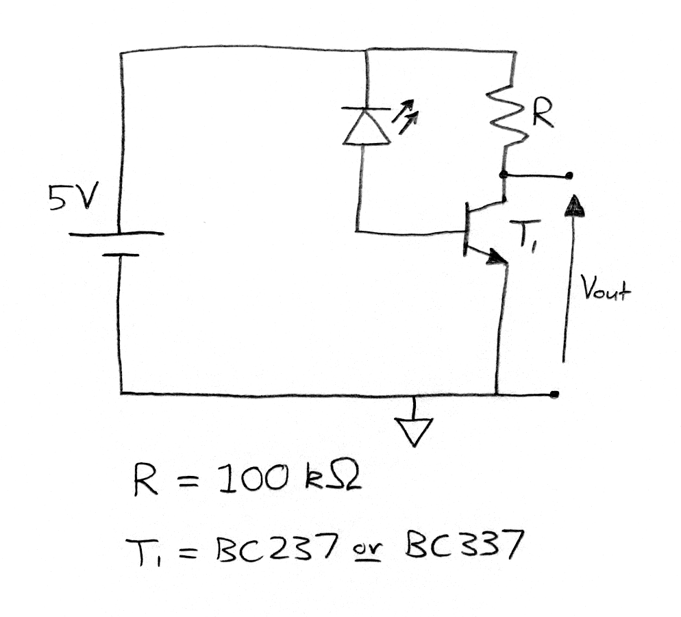
Open the Serial Plotter (under the Tools menu in the Arduino development environment) and you should see a waveform resembling the one below when you hold your LED photodetectors up to the flashing signal on the screen.

2021-22 Sem 2 Project 4: Power Factor Correction

Project duration: 2 weeks practical work + 1 week video production

Project type: group (3 per group)

In this project, you will work in teams to solve a very practical electrical engineering problem using the theory and tools we have been learning about for the last couple of weeks (e.g. phasors, impedance, MATLAB/Octave, LTspice). This project is designed to force you to do independent research on the topic of power in AC circuits and especially power factor correction.

The problem you need to solve is described below. Begin by discussing the problem description with your team and identifying knowledge gaps you need to fill. Then go and learn whatever you need to learn to solve the problem. Finally, present your solution in a group video presentation that will be uploaded to YouTube. We will screen all the videos together in class in the final lab session of the project.

Problem Description

On an island far from the mainland, a small power station (i.e. a voltage source) supplies 50 Hz AC power to a remote water pumping station via a long single-phase (i.e. 2 conductor) overhead power line. The power line cable is solid aluminium with a circular cross section. The pumping station can be modeled as a resistance in series with an inductance. The inductance and capacitance of the power line can be ignored, as can skin effect. However, the resistance of the power line will be significant, so it must be taken into account. Your first task is to analyse the power factor of the load (the pumping station) and calculate the losses in the power line. Your second task is to design a power factor correction solution for the pumping station and calculate the reduction in power line losses. Finally, you will present your work in a group video presentation.

The following information will be provided to your team (different values for each team):

  • VS : the r.m.s. voltage supplied by the power station
  • Rload : equivalent resistance of the pumping station
  • Lload : equivalent inductance of the pumping station
  • d : distance from the power station to the pumping station
  • D : diameter of the aluminium power line cable

Once your lab instructor assigns a number to your team, select your values from the list below.

Derek / Ted’s teams:

  • Team 1: VS =400 V r.m.s., Rload = 7.12 Ω, Lload = 12.9 mH, d = 2.5 km, D = 8.0 mm
  • Team 2: VS =380 V r.m.s., Rload = 7.42 Ω, Lload = 13.9 mH, d = 2.4 km, D = 7.0 mm
  • Team 3: VS =400 V r.m.s., Rload = 7.62 Ω, Lload = 12.9 mH, d = 2.6 km, D = 7.2 mm
  • Team 4: VS =380 V r.m.s., Rload = 7.02 Ω, Lload = 13.9 mH, d = 2.5 km, D = 7.8 mm

Kevin’s teams:

  • Team 5: VS =400 V r.m.s., Rload = 7.52 Ω, Lload = 13.9 mH, d = 2.6 km, D = 8.0 mm
  • Team 6: VS =380 V r.m.s., Rload = 7.22 Ω, Lload = 12.9 mH, d = 2.5 km, D = 7.0 mm
  • Team 7: VS =400 V r.m.s., Rload = 7.02 Ω, Lload = 13.9 mH, d = 2.4 km, D = 7.2 mm
  • Team 8: VS =380 V r.m.s., Rload = 7.32 Ω, Lload = 12.9 mH, d = 2.6 km, D = 7.8 mm

Suggested calculations

You will find it useful to calculate the values listed below. You may need to carry out some independent research to learn what some of these are.

  • Power factor of the RL load, cos(ϕ),
  • Load voltage phasor Vload and load current phasor Iload,
  • Complex, active, reactive and apparent power in the load (S, P, Q, and |S| respectively) before and after power factor correction,
  • The active power dissipated in the power line (Pline).

The following page summarises a lot of relevant background information:

https://voltageandcurrent.wordpress.com/ac-circuits/

Video Presentation

Specification:

  • One video per team.
  • Your video must be publicly visible on YouTube.
  • Minimum duration: 3 minutes.
  • Maximum duration: 5 minutes.
  • All team members must be clearly identified at the start of the video.
  • Every team member must present part of the video.

Content:

  • Show your analysis of the circuit (power station, power line, pumping station).
  • Show your calculation of the power factor in the load and the losses in the power line.
  • Show how your power factor correction solution reduces losses in the system and quantify those savings.
  • Prove that your solution works by including LTspice simulations of the system before and after power factor correction. Explain whatever you show.

Video assessment – marks will be awarded for:

  • Technical correctness and clarity.
  • Quality of spoken presentation.
  • Quality of visual presentation.
  • Complying with the specification and prescribed content listed above.
  • Individual contribution to the solution presented in the video.