Build an voltage oscillator circuit on a breadboard using an opamp.
Use an oscilloscope to debug and test your oscillator circuit.
Adapt the oscillator circuit to produce musical sounds from a loudspeaker.
This project comprises two parts:
Individual element: Initially, you will build and test a relaxation oscillator circuit on your breadboard (circuit diagram provided below). You will submit evidence of your working circuit in Brightspace (provisional deadline Wed 1 Dec 2021).
Team element: You will work with your teammates to develop an analog music synthesizer that you will use to perform a piece of music for a competition in the final week of the semester (week beginning Mon 13th Dec).
Further details about both elements of the project will be provided in class and this post will be updated in the coming days with details about what evidence you will need to submit.
This is the example circuit we looked at in class. An Arduino Nano reads signals from two TCRT5000 infrared reflective sensors and then control two DC motors via an SN754410NW quad half H-bridge integrated circuit (IC).
We also looked at the physical layout of the pins on the SN754410NE:
The two centre pins on each side of the chip are ground connections.
The pins either side of the ground pins are outputs.
Each output pin is controlled by the input pin right next to it (on the other side to the ground pin).
Corner pins 8 and 16 are connected to the positive voltage supply. Different voltages can be connected to these two pins where the motors require a higher voltage than the control circuit, but that is not the case here.
This code example illustrates the use of a new function to control the direction of both motors (forward, reverse or stop) with a single function call. The benefit of doing this is that the low-level details about which pins need to be set high and low are encapsulated in the motors function, which makes the loop function much more readable.
//
// 2-sensor control of Arduino robot
// Written by Ted Burke - last updated 17-Nov-2021
//

void setup()
{
  // motor control pins
  pinMode(2, OUTPUT); // left motor forward
  pinMode(3, OUTPUT); // left motor reverse
  pinMode(4, OUTPUT); // right motor forward
  pinMode(5, OUTPUT); // right motor reverse

  // Open serial connection to PC
  Serial.begin(9600);
}

void loop()
{
  motors(1,1); // left motor forward, right motor forward
  delay(2000);

  motors(-1,-1); // left motor reverse, right motor reverse
  delay(2000);

  motors(1,0); // left motor forward, right motor stop
  delay(2000);
}

// This function sets the direction of both motors
void motors(int left, int right)
{
  // Control left motor
  if (left > 0)
  {
    digitalWrite(2, HIGH); // left motor forward
    digitalWrite(3, LOW);
  }
  else if (left < 0)
  {
    digitalWrite(2, LOW);  // left motor reverse
    digitalWrite(3, HIGH);
  }
  else
  {
    digitalWrite(2, LOW);  // left motor stop
    digitalWrite(3, LOW);
  }

  // Control right motor
  if (right > 0)
  {
    digitalWrite(4, HIGH); // right forward
    digitalWrite(5, LOW);
  }
  else if (right < 0)
  {
    digitalWrite(4, LOW);  // right motor reverse
    digitalWrite(5, HIGH);
  }
  else
  {
    digitalWrite(4, LOW);  // right motor stop
    digitalWrite(5, LOW);
  }
}
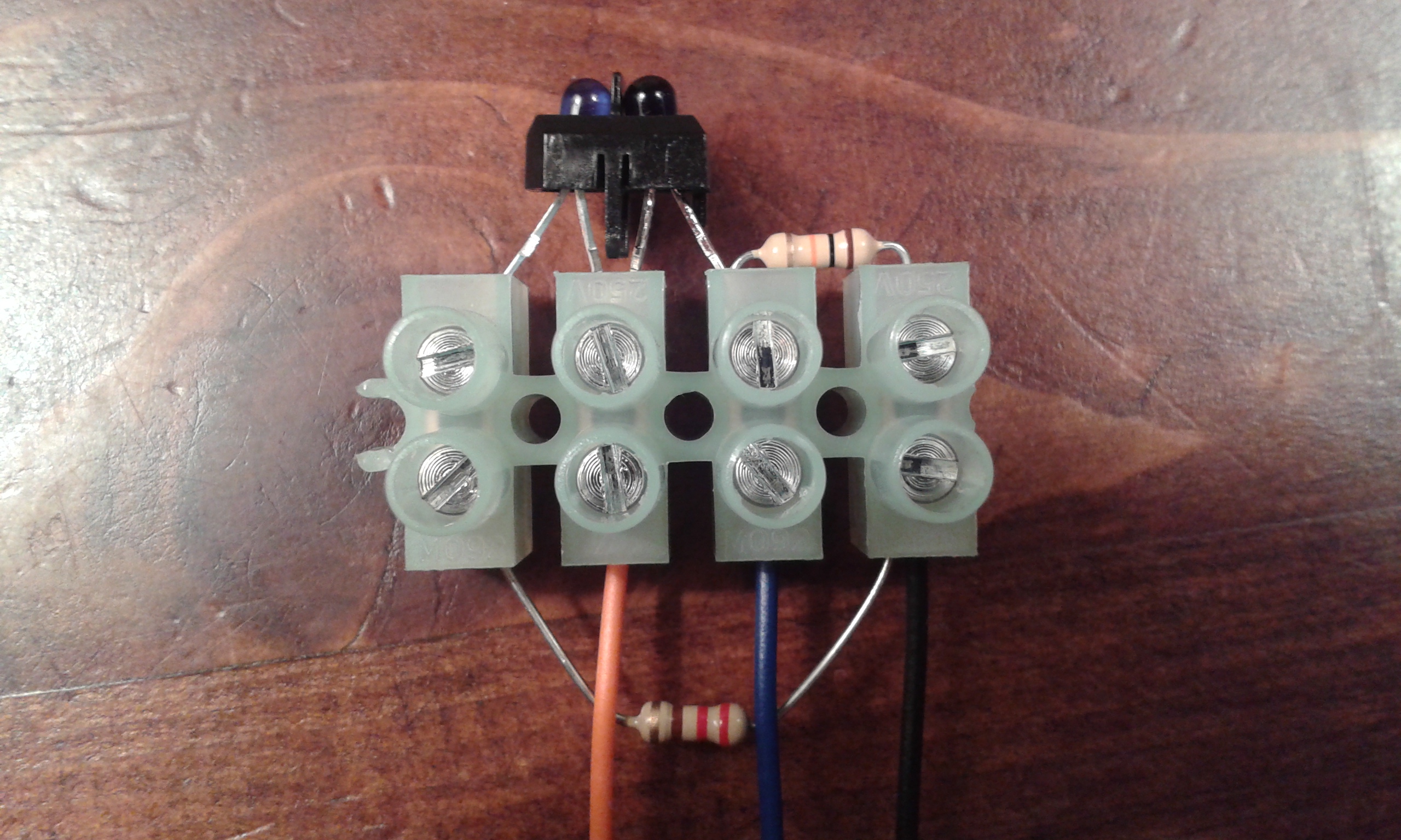
The TCRT5000 is an infrared reflective sensor in a small black plastic casing with four legs, with one “blue eye” and one “black eye”. The blue eye is an infrared LED which emits a beam of infrared light when electric current flows through it. The black eye is a phototransistor which detects infrared light. When the sensor is close to a surface, some of the emitted light is reflected back and detected by the phototransistor, but the amount of light reflected back depends on the colour of the surface. This can be used to sense the colour of a surface. This article explains how to use the TCRT5000 (with resistors, wires and terminal block) to build a 3-wire colour sensing module.
Lay out the parts shown in the image below. The three wires visible at the bottom of the image are the long red, blue and black wires.
“TCRT5000” is written in tiny letters on one side of the colour sensor – make sure that side is facing downwards (towards the table).
The two legs of the TCRT5000 that are now higher off the table (i.e. closer to the camera in the image below) should be carefully bent towards each other until they meet.
Insert the components and wires into the terminal block as shown in the images below and tighten each terminal with a screwdriver to hold them all in place.
To connect the sensor module to an Arduino breadboard circuit, connect the three wires as follows:
Connect the red wire to the positive (red) rail.
Connect the black wire to the negative (blue) rail.
Connect the blue wire to an analog input pin on the Arduino, e.g. pin A0.
In this team project, you will work in a team of three to design and build a small autonomous robot vehicle to compete in a time trial (TT) competition. The robot will have to navigate autonomously along a clearly marked winding track from one end to the other. The project will conclude with a competition in which we measure how long it takes each team’s robot to complete the task. Your team will record a 3-minute video presentation describing the design of your robot.
The project will include the following elements (among others):
Arduino programming
Motor control
Mechanical design
Use of one or more TCRT5000 infrared sensors to detect the track
The project grade will be based on three factors:
Performance of your team’s robot in the competition
Quality of your presentation
Tutor observation of your individual contribution to the group work process
Video presentation guidelines:
Each team member must present one minute (60 seconds) of the team video.
Most teams will have three members, but teams with two or four members can adjust the overall video duration so that each team member presents for 60 seconds. Teams with two members may, if they wish, extend each student’s presentation time to 90 seconds.
The team should agree in advance what topics each team member will cover.
It’s up to each team member whether they are visible in the video, but every team member must speak in their section of the video. Quality of spoken presentation will be an element in the formal grade.
Quality of visual presentation will be an element in the formal grade.
Your team video must be uploaded to YouTube and set as publicly visible. It can be unlisted. Each team member will confirm that they contributed to the team video by submitting the YouTube link to Brightspace (same link for all team members).
Results will be ranked based on the time taken by each robot to complete the task (as measured by the referee), as well as compliance with the rules set out below.
Competitors are permitted (at the discretion of the referee) to attempt the task multiple times, whether to complete the task for the first time, or to improve upon a previously recorded attempt. Priority may be given to competitors who have not yet recorded a successful attempt.
The track will be a dark stripe on a light-coloured background.
At the beginning of a time trial attempt, the team places their robot over the start end of the stripe. Some part of the robot must be directly above the end of the track when the referee starts the clock.
The robot follows the track from the start to the finish end of the stripe, keeping some part of itself directly above the stripe at all times. Competitors are forbidden from touching or otherwise influencing the robot during the time trial – the robot must be complete the task autonomously.
The clock stops as soon as any part of the robot is directly above the finish end of the stripe. The robot does not need to come to a halt.
If the robot leaves the track at any point (i.e. no part of the robot is directly above the track), that attempt at the time trial is null and void.
The Track
The track will be marked with a clearly visible stripe on a horizontal surface.
The track will be a dark stripe on a light background.
The width of the stripe will be no less than 4cm and no greater than 6cm.
The track consists of five straight sections, each at least 50cm in length.
At every meeting point between two straight sections, the track turns a right-angled corner (i.e. 90 degrees). At each corner, the inner and outer edges of the track will each form a 90 degree angle (i.e. neither edge of the track is rounded at the corner).
As the robot travels along the track from beginning to end, the corners are as follows: left turn, left turn, right turn, right turn.
The recorded result for the time trial will be the time elapsed between the last moment when the robot was above the start end of the stripe and the first moment when the robot is above the finishing end of the stripe.
The robot must remain in contact with the horizontal surface throughout the time trial.
It is not permitted to touch, influence or otherwise interfere with the robot during the time trial – it must operate completely autonomously.
If the robot leaves the track at any point during the time trial, that attempt is null and void. The robot does not need to be in physical contact with the track throughout the attempt, but some part of the robot must always be directly above some part of the track.
Robot specification
The maximum permitted size of the robot is a cube 150 mm on all sides (i.e. 150 mm × 150 mm × 150 mm). At every moment during an attempt, every single part of the robot (including loose wires, etc.) must fit within an upright 150 x 150 x 150 mm cube. Upright means that two sides of the cube are horizontal and four sides are vertical. Note that this size limit is very strictly enforced.
The maximum permitted mass of the robot is 500 g. This weight limit is strictly enforced.
The only permitted power source for the robot is 4 × AA batteries (e.g. the battery pack provided in the RoboSumo kit).
Competitors are permitted to source additional components and materials for use in their robot, at their own expense. However, the maximum permitted budget for parts used in a robot during the time trial is €20 (of the competitors’ own money). This excludes the cost of parts supplied by the college and materials that were obtained for free (provided that similar materials could easily be obtained for free by other competitors). Note that you do not need to spend any money to complete this challenge. Also, please note that any money you choose to spend will not be reimbursed by the college.
Non-compliant robots and late entries
Robots that fail to comply with the above specifications may still be permitted to record a ranked time, at the discretion of the referee. However, their results will be ranked below those of compliant robots that completed the task in the same week, irrespective of the time recorded.
Results for teams that complete the task after the end of the formal competition may, at the discretion of the referees, be added to the ranking. However, they will be ranked below teams that completed the challenge during the competition, unless some exceptional circumstances apply (e.g. certified medical absence).
Example TrackTT video
Note that the following video shows a white track on a dark background, but the track used in this project will be a black track on a light-coloured background.
Summary of ranking criteria:
Ranking of results will be according to the following criteria, in order of decreasing precedence:
Robots that are fully compliant with the above robot specification during their ranked attempt will rank above robots that are non-compliant during their ranked attempt.
Robots will be ranked according to the time taken to complete the task. Robots that complete it quicker will be ranked higher.
Referees and conduct of competitors
Every EEPP module lecturer is a competition referee. The module lecturers may also nominate additional referees.
Competitors must follow the referee’s instructions during an attempt.
Competitors who repeatedly fail to follow the referee’s instructions, or who engage in rude or offensive behaviour during the competition may be suspended or disqualified at the discretion of the referee(s).
The referees will aim to treat all competitors fairly. Where a difference of opinion arises, competitors must always respect the decision of the referee. Once the referee makes a decision, competitors must refrain from further argument on the matter.
The referees reserve the right to amend the competition rules or ranking criteria in individual cases, should the need arise (e.g. where a student is absent for medical reasons). Amendments may be applied at the time of the competition or subsequently, which may affect the competition ranking.