2021-22 Sem 1 Project 3: Motor control

Expected project duration: 1 week (i.e. 2 lab sessions)

At the end of this project, you should be able to:

  • Solder wires onto the terminals of a motor.
  • Perform unidirectional speed control of a DC motor using an Arduino and a MOSFET transistor.
  • Perform bi-directional speed control of a DC motor using an Arduino and an SN754410 driver IC.
  • Use an oscilloscope to visualise oscillating electrical voltage signals.

There are three items to be submitted to Brightspace for assessment:

  1. A Word document containing the following evidence (additional details below):
    • Photo of the wires soldered onto your motor.
    • Photo of your breadboard circuit for Task 1.
    • Working code for Task 1.
    • Photo of your breadboard circuit for Task 2.
    • Working code for Task 2.
  2. A link to a YouTube video showing that Task 1 is complete (details below).
  3. A link to a YouTube video showing that Task 2 is complete (details below).

Project Description

In this project, we explore two ways of controlling a motor with a program running on a microcontroller. In the first task, we use a MOSFET transistor to interface the motor to the Arduino Nano in a way that facilitates unidirectional speed control. In the second task, we use a driver IC to perform bi-directional control of the motor. You will also learn to do some simple soldering and to visualise oscillating electrical signals on an oscilloscope.

Task 1: Unidirectional control of a DC motor

The video below provides some background information for this task.

Perform the following steps:

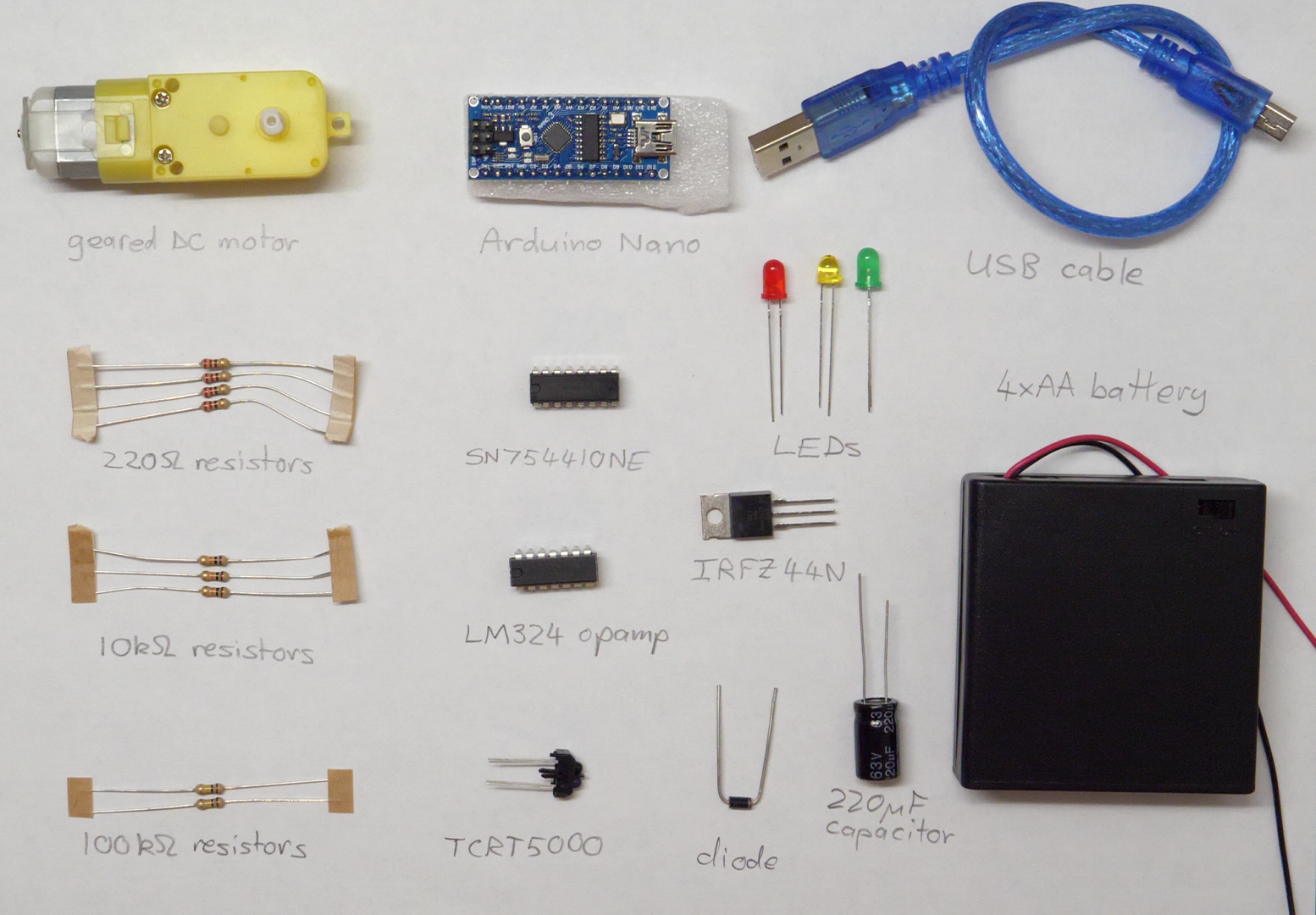
  1. Solder 20 cm long wires onto the terminals of your motor. You can choose whatever wire colour you like, apart from red or black.
  2. Find the datasheet for the IRFZ44N transistor online, so that you can identify which pin is which.
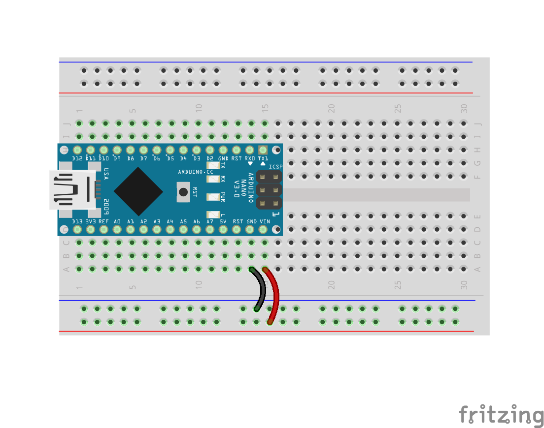
  3. Build the circuit shown in the diagram above on a breadboard. The circuit should be neat and the wires should be appropriately colour-coded. Please pay special attention to correct use of red and black wires.
  4. Program the Arduino to perform the following sequence of LED and motor actions:
    1. LED off and motor driving at 25% duty cycle for 2 seconds.
    2. LED off and motor driving at 50% duty cycle for 2 seconds.
    3. LED off and motor driving at 100% duty cycle for 2 seconds.
    4. LED on and motor stopped for 4 seconds.
  5. Use the oscilloscope to visualise the pulsed signal being emitted from Arduino pin D3. Your lecturer will demonstrate how to do this in the lab.
  6. Record a video showing your circuit performing the above sequence, followed by the oscilloscope displaying the pulsed signal from pin D3 for each state of the system.
  7. Upload the video to YouTube and submit the link to the Brightspace assignment.
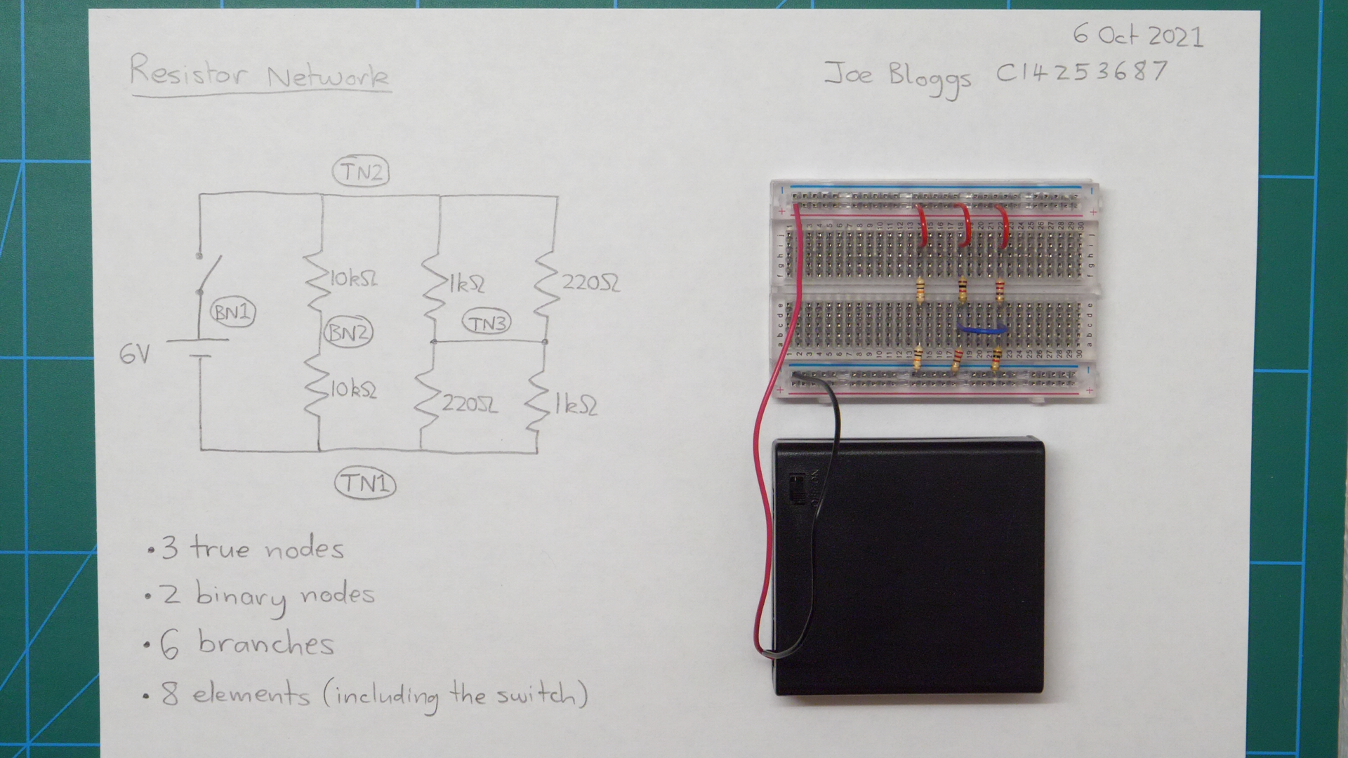
  8. Open a new Word document. Insert a heading with your name, student number, the date, the name of this module and the title of this project.
  9. Take a clear photograph of the wires soldered to your motor and add it to the Word document.
  10. Take a clear photograph of your breadboard circuit and add it to your Word document.
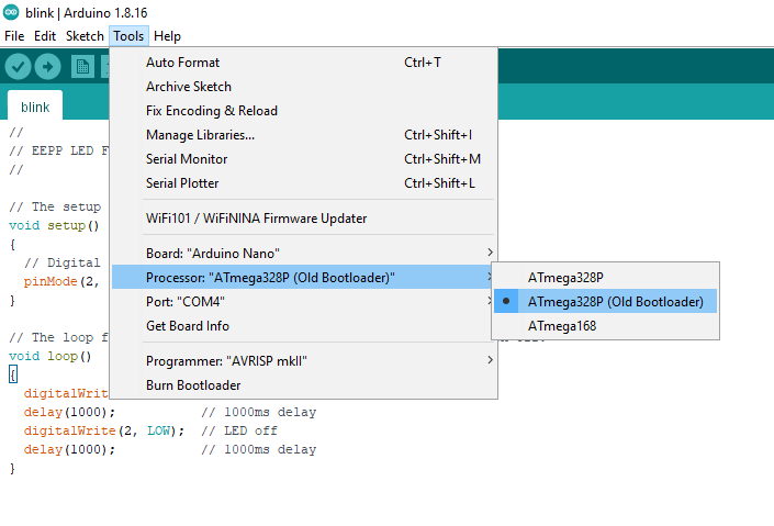
  11. Add your working Arduino code for Task 1 to the Word document. Ensure it is neatly formatted and includes clear and accurate comments.

Task 2: Bi-directional control of a DC motor

The videos below provide background information for this task.

Perform the following steps:

  1. Find the datasheet for the SN754410 IC online and use it to identify the correct pin for each connection to the chip. Try googling “SN754410 datasheet” and look for a PDF result.
  2. Build the circuit shown in the diagram above on a breadboard. Note that the final connection between Arduino pin D6 and pin 9 on the SN754410 chip is not shown in the diagram above, but must be included in your circuit to facilitate speed control (as explained in the video). The circuit should be neat and wires should be appropriately colour-coded (please pay special attention to correct use of red and black wires).
  3. Program the Arduino to perform the following sequence of LED and motor actions:
    • LED off and motor driving forward at 50% duty cycle for 3 seconds.
    • LED on and motor driving forward at 100% duty cycle for 2 seconds.
    • LED off and motor stopped for 3 seconds.
    • LED off and motor driving in reverse at 50% duty cycle for 3 seconds.
    • LED on and motor driving in reverse at 100% duty cycle for 2 seconds.
    • LED off and motor stopped for 3 seconds.
  4. Use the oscilloscope to visualise the pulsed signal being emitted from Arduino pin D6.
  5. Record a video showing your circuit performing the above sequence, followed by the oscilloscope displaying the pulsed signal from pin D6 for each state of the system.
  6. Upload the video to YouTube and submit the link to the Brightspace assignment.
  7. Take a clear photograph of your breadboard circuit and add it to your Word document.
  8. Add your working Arduino code for Task 2 to the Word document. Ensure it is neatly formatted and includes clear and accurate comments.
  9. Submit your Word document to the Brightspace assignment.

2021-22 Sem 1 Project 2: LED Flash Challenge

Expected project duration: 1 week (i.e. 2 lab sessions)

At the end of this project, you should be able to:

  • Build a simple breadboard circuit with the Arduino nano microcontroller development board,
  • Write simple programs to run on the Arduino Nano,
  • Configure Arduino pins as digital outputs and set their voltages high and low (e.g. to switch LEDs on and off).
  • Convert between decimal and binary numbers.

There are four items to be submitted to Brightspace for assessment:

  1. Screenshot of the LED Flash Challenge validator web page displaying the congratulations message with your correct team number.
  2. A photo of your breadboard circuit.
  3. The .ino file containing your complete working code. Your code should be neat, correctly indented and clearly commented.
  4. A link to a YouTube video showing your all of your team’s circuits working at the same time. You can use your battery pack to power your circuit when it’s plugged out from the PC. One YouTube video for the whole team is sufficient, but every team member should upload the link to the video.

Project Description

This project is a short competitive puzzle called the LED Flash Challenge. In this challenge, doing well means two things: getting it working quickly and, more importantly, trying to understand what you’re doing.

You’ll work in a team to solve this puzzle and complete the challenge, but each member of your team will build and program his/her own Arduino circuit. The challenge consists of two tasks:

  1. Build a simple breadboard circuit for the Arduino Nano and program it to blink a light-emitting diode (LED) on and off.
  2. Add a second LED to the circuit and reprogram the Arduino to transmit your team number as a binary sequence using a series of LED flashes.

The first task is very prescriptive, which means that we’ll basically tell you exactly what to do, but to complete the second task you’ll need to think for yourselves. To complete the second task, you will require a team number – this will be assigned to you by your lecturer.

Task 1: Blinking LED

This task is relatively straightforward and shouldn’t take you too long to get working. Before beginning, make sure your breadboard is the same way around as the picture below.

The first component in the circuit is the Arduino Nano, which is a simple computer in a tiny package. In the coming weeks, we will program the Arduino to read signals from different sensors and to control motors and electromagnetic coils. In this project, you will use the Arduino to control some flashing LEDs.

Make sure your Arduino is the right way around, with the mini USB socket at the end of the breadboard (row 1). Place the breadboard flat on a hard surface before pushing the Arduino into the board. The pin marked D12 should be in breadboard hole H1. Some Arduinos can be very difficult to insert into the breadboard, so if you’re having problems just ask for help because you might have just received a particularly tricky one.

As we learned previously, on each side of the breadboard there are two long rows of holes which are connected along the full length of the board. These rails are used to distribute the supply voltage to different parts of the circuit. The blue line marks the negative rail (0V); the red line marks the positive rail (5V in this circuit). The Arduino draws its power from these rails.

  • Connect a short black wire between A14 and the negative (blue) rail.
  • Connect a short red wire between A15 and the positive (red) rail.

The first thing we’ll control with the Arduino is a green light-emitting diode (LED). To do this, we’ll turn the Arduino pin marked D2 into a digital output which means that the program running on the Arduino can set it high (5V) or low (0V). When the pin is set high, a small electrical current flows through the green wire, through the green LED, and finally through the resistor to ground (the negative rail).

  • Insert a green wire between I11 and A18.
  • Insert a green LED between E18 and E19. The LED is a one-way valve for electricity, so it must be the right way around. Inside the green plastic bead, if you look carefully you’ll see that each leg is connected to a kind of a flat plate. As shown in the image below, the leg connected to the larger plate should be in E19.
  • Insert a 220 Ω resistor (colour code  REDREDBROWNGOLD ) with short legs between B19 and the negative (blue) rail.

We’re ready to run a program on the Arduino to flash the green LED on and off.

  • Double-click the Arduino icon on the desktop to launch the Arduino IDE (integrated development environment).
  • NOTE: If you’re working on your own laptop, you can download the Arduino IDE from https://www.arduino.cc/en/software (be sure to select the download for “Windows Win 7 and newer“).
  • Delete the example code that appears by default in the editor.
  • Type the following code into the Arduino IDE editor.

Before running the program on the Arduino Nano, you need to select the correct version of Arduino.

  • Under the “Tools” menu, enter the “Board” sub-menu and select “Arduino Nano” or “Arduino Nano w/ ATmega328” as shown in the image below.
  • Under the “Tools” menu, enter the “Processor” sub-menu and select “ATmega328P (Old Bootloader)”.
  • Under the “Tools” menu, enter the “Port” (or “Serial Port”) sub-menu and select whatever COM device is listed there, as shown below. If the “Port”/”Serial Port” sub-menu is not accessible, please ask your lecturer to check your machine because the Arduino drivers may not be correctly installed.

To download and run the program on the Arduino, click the right-facing arrow button on the toolbar of the Arduino IDE:

At this point you should hopefully see the green LED flashing on and off slowly. If it’s not flashing and you can’t figure out why, please ask your lecturer to check what’s wrong.

Once your LED is blinking, there are four things you need to understand in the code before moving on:

  1. How one of the Arduino pins (D2) was turned into a digital output.
  2. How the LED is turned on.
  3. How the LED is turned off.
  4. How to delay the program for a specified number of milliseconds, so that the rate of the LED blinking can be controlled.

Once you understand these four things, you have finished this part of the task (the easy part) and it’s time to move on to the main part of the LED Flash Challenge.

Task 2:

In this part, you’re going to modify your circuit to create a simple optical transmitter, which transmits a digital message (a sequence of 1s and 0s) as a series of LED flashes.

The message that you’ll transmit will be 2 bytes long (a byte is 8 bits, or 8 ones and zeros) and it will contain your team number (byte 1) followed by a second number, which is calculated by subtracting your team number from 255 (byte 2).

For example, if your team number is 79…

  • byte1 = 79
  • byte2 = 255 – 79 = 176
  • byte1 + byte2 = 255

Here, let me explain how binary numbers work…

Try doing some independent research on binary numbers. You’ll find a lot more great stuff on YouTubeWikipedia, etc.

Specifically, you need to do the following:

  1. Modify the code to create a second digital output pin.
  2. Extend the circuit by adding a second LED (with current limiting resistor) to that digital output pin.
  3. Convert your team number into an 8-bit binary number. This is byte 1 of your message.
  4. Calculate the required value of byte 2 (so that byte1+byte2 = 255) and write it as an 8-bit binary number.
  5. Each byte will be transmitted as a sequence of ones and zeros, preceded by a start bit (1) and followed by a stop bit (0). That means your complete transmission will be 20 bits long. You should calculate this sequence ad write it down on paper first.
  6. To transmit a 1, turn LED1 off and LED2 on for 500ms.
  7. To transmit a 0, turn LED1 on and LED2 off for 500ms.
  8. To ensure the sequence is read correctly, transmit a long sequence of zeros (for about 5 seconds) before you transmit your message.
  9. As is typically the case in digital transmissions, each byte must be transmitted least significant bit first.

Let’s consider that example team number 79 again. As explained above, byte 1 is 79 and byte 2 is 176.

  • Before transmitting the sequence, send a “0” for about 5 seconds.
  • The first bit of the sequence is the start bit for byte 1 which is “1”.
  • Written as a binary number, 79 (seventy-nine) is 0b01001111. The “0b” prefix indicates that a number is being written in binary form – it’s not part of the number value. The byte is transmitted least significant bit first, i.e. in the following order: “1,1,1,1,0,0,1,0”.
  • The next bit is the stop bit for byte 1, which is “0”.
  • The next bit is the start bit for byte 2, which is “1”.
  • Written as a binary number, 216 is 0b10110000, so the next 8 bits are “0,0,0,0,1,1,0,1”.
  • The final bit is the stop bit for byte 2, which is “0”.

To summarise, the complete 20-bit sequence for team 79 would be as follows:

To check your transmission is correct, use the LED Flash Challenge web validator:

When the validator detects a team number, it displays a message similar to that shown below (the team number will vary). Note that the breadboard circuit is held still in front of the camera with one LED in each of the red boxes.

You are welcome to try the validator on your own laptop / PC if it has a camera. In principle, it should work on most modern PCs with a webcam and up-to-date browser. The current release of Google Chrome seems to run it without problems. It can also be used with the web browser on some phones.

Remember to submit the four items of evidence listed at the beginning of this post to Brightspace.

2021-22 Sem 1 Project 1: Breadboard circuits

Expected project duration: 1 week (i.e. 2 lab sessions)

In the lab sessions for this module, we undertake a series of projects. Some are individual projects; others are group projects. We begin with an individual project to get you started building and understanding electrical circuits.

At the end of this project, you should be able to:

  • Understand circuit diagrams,
  • Identify elements, binary nodes, true nodes and branches in a circuit diagram,
  • Draw basic circuit diagrams by hand,
  • Translate a circuit diagram into a neat and fully functioning breadboard circuit,
  • Find an electronic component’s datasheet online and use it to identify each of its pins/terminals.

Items to be submitted to Brightspace for assessment:

  • Four evidence photos – one for each of the four circuits shown below.

Component Kit

In today’s lab, you will receive a component kit that you must look after for the duration of the module. You will reuse these components for several projects, so please look after them all carefully. The kit contains:

  • 1 × mini breadboard – This is used to build electrical circuits. It allows us to create electrical connections between components without the need for soldering.
  • 1 × Arduino Nano microcontroller development board
  • 1 × mini USB cable
  • 4 × AA battery pack
  • 1 × geared DC motor
  • 1 × SN754410NE IC
  • 1 × LM324 quad opamp IC
  • 1 × IRFZ44N MOSFET transistor
  • 1 × TCRT5000 infrared reflective sensor
  • 1 × 1N4004 power diode
  • 1 × red LED
  • 1 × green LED
  • 1 × yellow LED
  • 4 × 220 Ω resistor
  • 3 × 10 kΩ resistor
  • 2 × 100 kΩ resistor
  • 1 × 220 μF capacitor

Abbreviations used above:

  • DC: direct current (as opposed to alternating current)
  • IC: integrated circuit (another name for a microchip)
  • LED: light-emitting diode
  • MOSFET: metal-oxide-semiconductor field-effect transistor
  • opamp: operational amplifier

The breadboard is shown below. When two wires (or component legs/pins) are plugged into the same short row of five holes, they are electrically connected together by a conducting metal clip that sits under the surface of the board. The rows on each side of the board are numbered from 1 to 30.

On each side of the breadboard, there are two long rails – continuous electrical connections from one end of the board to the other. These rails are marked by the long red and blue lines on the upper surface of the board. Two wires plugged in anywhere on the same rail will be connected together electrically. The rails are typically used to distribute supply voltage around the board without the need for long wires.

When inserting wires or components into the breadboard, it is desirable to minimise the amount of exposed metal, so that short circuits are less likely to occur. Two neat ways of inserting a resistor into a breadboard are shown below. Connections between different parts of the breadboard can be made with insulated single-core wires.

Colour coding of wires:

  • Use red wires for nodes in the circuit that are always at the positive supply voltage (e.g. 6 V for the example circuits below). Never use red wire for any other nodes.
  • Use black wires for nodes in the circuit that are always at the negative supply voltage (normally 0 V). Never use black wire for any other nodes.
  • Electricity doesn’t care what colour a wire is, but because black and red are universally understood to have the above meanings, it is extremely confusing and potentially dangerous to deviate from that convention.
  • There are no fixed rules for other wire colours in breadboard circuits, but adopting a logical pattern in your colour coding can be very helpful when troubleshooting.

Additional components and materials will be supplied throughout the module, according to the requirements of each project.

Project Description

Four electrical circuit diagrams are provided below. For each circuit, you will do the following:

  • Redraw the circuit diagram by hand on a blank (i.e. without lines) sheet of A4 paper.
  • Write the number of true nodes on the page. Label the true nodes TN0, TN1, TN2, etc.
  • Write the number of binary nodes on the page. Label the binary nodes BN1, BN2, etc.
  • Write the number of branches on the page.
  • Write your name and student number on the page and add a title.
  • Build the circuit on the breadboard.
  • Place the completed breadboard circuit on the page and take a photo showing all of the above items very clearly. An example photo is shown below for an example circuit.
  • As evidence of your work, submit your photo to the assignment that has been created for this project in the EEPP1 Brightspace module.

The assessment for this project will be based primarily on the (up to) four evidence photos that you submit. Marks will be awarded for each circuit completed (or partially completed). Your mark for each circuit will depend on the technical correctness of your work, as well as the quality of presentation (e.g. clear photograph, neat breadboard circuit, neat circuit diagram, other required information displayed clearly, etc.).

You may not have time to complete all four circuits. That’s okay – we’ll just assess whatever number of circuits you get done. Please upload the evidence photo for each completed circuit before moving on to the next one.

Example circuit: Resistor network

DO NOT BUILD THIS CIRCUIT! It is just provided as an example to show you what kind of photo we want you to submit for each of the circuits below.

If you were provided with this circuit diagram…

…we would want you to submit a photo that looks like this:

Circuit 1: Three parallel LEDs

This circuit drives current through three LEDs, which should cause them to emit light. However, one of the LEDs in this circuit will be very dim compared to the other two. Can you see why?

Submit a clear photo of your completed breadboard circuit and information page.

Circuit 2: Two LEDs in series

Submit a clear photo of your completed breadboard circuit and information page.

Circuit 3: Resistor ladders

This circuit contains three “resistor ladders” (basically just two or more resistors in series).

In addition to the normal items required on the information page, measure voltages V1, V2 and V3 using a multimeter and write these on the page also. Your lecturer will show you how to use the multimeter (provided one is available in your classroom).

Submit a clear photo of your completed breadboard circuit and information page.

Circuit 4: Infrared proximity sensor circuit

This circuit lights a green LED whenever an object is in close proximity to the TCRT5000 infrared sensor.

To construct this circuit, you will need to download the datasheets for the TCRT5000 infrared sensor and the LM324 opamp IC. A datasheet is a document provided by the manufacturer of a component containing lots of useful information including the pinout, which shows which pins are which. Without the pinout, you won’t know how to connect the TCRT5000 or LM324.

To find the datasheet for any component, just google the name of the component (which is usually written somewhere on the component) together with the word “datasheet” and then look for a PDF result. Your lecturer can help you with this if you’re having trouble finding either of the datasheets you need or making sense of them.

Submit a clear photo of your completed breadboard circuit and information page.