In this lab, you will work in teams to simulate two well-known circuits in LTspice. In each case, your objective is to replicate a provided screenshot, including a plot showing the result of a circuit simulation. To make the task more difficult, the value of a capacitor has been concealed in each screenshot. You may find it useful to do some impedance calculations in Octave / MATLAB to identify the correct capacitance value for each circuit.
As discussed in previous lectures, each of the three fundamental linear circuit elements can be converted to an impedance:

where
- ZR is the impedance of a resistor [Ω]
- R is resistance [Ω]
- ZL is the impedance of an inductor [Ω]
- L is inductance [H]
- ZC is the impedance of a capacitor [Ω]
- C is capacitance [F]
- ω is angular frequency [rad/s]
- j is the imaginary unit – i.e.

Impedances in series
Two or more impedances in series can be combined into a single equivalent impedance, Zeq, simply by adding them up:

Impedances in parallel
Two impedances in parallel, Z1 and Z2, can be combined into a single equivalent impedance, Zeq, as follows.

or equivalently

Part 1: Series resonant RLC circuit
This circuit includes an inductance and capacitance in series, which causes it to resonate at one particular frequency (100 Hz in this case). The reactance of an inductor is positive, but the reactance of capacitor is negative. Both reactance values depend on frequency. When the frequency is just right, the two reactances cancel each other out perfectly, leaving only the small resistance to limit the current in the circuit. This is called the resonant frequency of the circuit.
The impedance of a series resonant RLC circuit is minimised at its resonant frequency.

Working with your teammates, replicate the screenshot shown above as precisely as you can. Please note the following:
- The simulation type is set to “AC Analysis”. This produces a plot with frequency on the horizontal axis, showing how the circuit responds over a range of frequencies.
- The label showing the capacitor value has been erased from the screenshot above, but it should be visible in your screenshot. You will have to figure out the value of the capacitor, for example by doing impedance calculations in Octave / MATLAB.
- Set the background colour of the circuit diagram to white.
- Add your name and the names of your teammates to the schematic (in place of the example names shown above).
SUBMISSION ITEM 1: Submit your LTspice screenshot of the series resonant circuit to Brightspace. Ensure your screenshot is as close as possible to the original example screenshot. Ensure that it includes your names. Although you are working in teams, each individual student should submit their own screenshot to Brightspace.
Part 2: Parallel resonant RLC circuit
This circuit features an inductor and a capacitor in parallel. Any actual physical inductor has some non-zero resistance, so a small resistance is included here in series with the inductor. Like the previous circuit, this one resonates at one particular frequency (1.8766 kHz in this case) and its impedance is purely real at that frequency (i.e. no imaginary part / zero reactance). However, unlike the series resonant circuit, the impedance of a parallel resonant RLC circuit is maximised at its resonant frequency.

Working with your teammates, replicate the screenshot shown above as precisely as you can. Please note the following:
- The label showing the capacitor value has been erased from the screenshot above, but it should be visible in your screenshot. Try to calculate the value of the capacitor, for example using Octave / MATLAB.
- Set the background colour of the circuit schematic to white.
- Add your name and the names of your teammates to the schematic.
SUBMISSION ITEM 2: Submit your LTspice screenshot of the parallel resonant circuit to Brightspace. Ensure your screenshot is as close as possible to the original example screenshot. Ensure that it includes your names. Although you are working in teams, each individual student should submit their own screenshot to Brightspace.
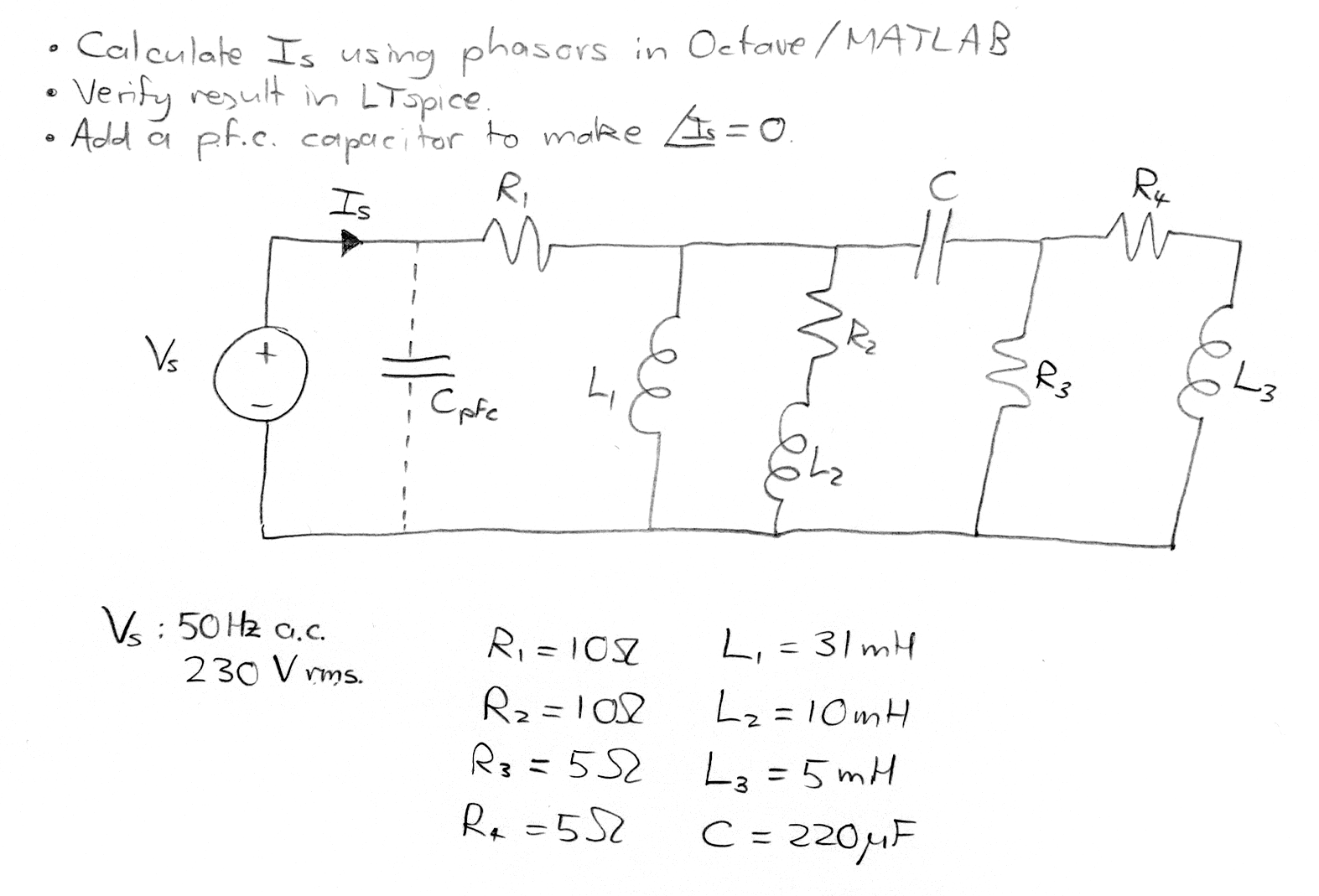
Part 3: Extra circuit analysis exercise
If you finish parts 1 and 2 before the end of class, have a go at this additional circuit analysis problem. Cpfc is a power factor correction capacitor – do not include it for the initial calculation, but once you have calculated Is and the total equivalent impedance, calculate the required value of Cpfc to bring Is perfectly into phase with Vs.